Reducing the total cost of ownership (TCO) for breathing air compressor systems is essential for organizations seeking to optimize their operational efficiency and minimize expenses. This article will explore effective strategies that focus on energy efficiency, maintenance practices, and system reliability. By understanding these key areas, businesses can significantly lower their TCO while ensuring that their compressor systems operate at peak performance. The following sections will delve into specific methods for improving energy efficiency, optimizing maintenance practices, and ensuring system reliability, all of which contribute to a more cost-effective operation.
Improving Energy Efficiency
Enhancing energy efficiency in breathing air compressor systems is crucial for reducing operational costs. Energy-efficient technologies, such as Variable Speed Drive compressors and Heat Recovery Systems, can significantly lower energy consumption. By optimizing pressure settings and implementing heat recovery systems, organizations can achieve substantial savings on energy bills.
Research consistently demonstrates the substantial energy savings achievable through the implementation of variable speed drive technology in compressed air systems.
Variable Speed Drives for Energy Saving in Compressed Air Systems
energy saving in compressed air systems in different companies. A variable speed driven compressor needs a professional design from the first draft of the compressor.
The benefits of variable speed drive for air compressors, 2005
For instance, investing in energy-efficient technologies not only reduces energy costs but also minimizes the environmental impact of compressor operations. This dual benefit makes energy efficiency a top priority for businesses looking to improve their bottom line.
Technologies That Enhance Energy Performance
Several technologies can enhance the energy performance of breathing air compressors:
Variable Speed Drive Compressors: These compressors adjust their speed based on demand, leading to significant energy savings.
Heat Recovery Systems: By capturing waste heat from the compressor, these systems can be repurposed for heating water or space, further reducing energy costs.
Smart Monitoring Systems: These systems provide real-time data on energy usage, allowing for better management and optimization of compressor operations.
Implementing these technologies can lead to a marked reduction in energy consumption, directly impacting the TCO of breathing air compressor systems.
Further research highlights the importance of advanced monitoring and diagnostic methods, particularly those integrated with variable speed drives, for optimizing compressor performance and ensuring air quality.
Monitoring & Diagnostics for Breathing Air Compressor Systems
methods for compressed-air systems powered by twin-screw compressors. The first introduced variable-speed-drive-based monitoring and diagnostic methods for pump, compressor, and fan systems. In addition, filters ensure that as few particles as possible end up in the air breathed by building occupants.
Variable-speed-drive-based monitoring and diagnostic methods for pump, compressor, and fan systems, S Pöyhönen, 2021
Optimizing Maintenance Practices
Regular maintenance is vital for ensuring the longevity and efficiency of breathing air compressor systems. Establishing a preventive maintenance schedule can help identify potential issues before they escalate into costly repairs. Additionally, adopting predictive maintenance strategies can further enhance reliability and reduce downtime.
Studies emphasize the effectiveness of predictive maintenance solutions in monitoring various components and predicting potential faults in air compressors.
Predictive Maintenance for Air Compressor Condition Monitoring
Predictive maintenance (PdM) solution for condition monitoring and fault prediction for the exhaust valve, bearings, water pump, and radiator of an air compressor.
An explainable deep learning-based predictive maintenance solution for air compressor condition monitoring, A Ciobotaru, 2025
Keeping detailed maintenance logs is essential for tracking the performance and service history of compressor systems. This practice not only aids in compliance with safety standards but also helps in planning future maintenance activities effectively.
Best Practices for Maintenance Cost Reduction
To optimize maintenance practices and reduce costs, consider the following best practices:
Routine Inspections: Regular checks can identify wear and tear early, preventing more significant issues.
Scheduled Maintenance: Adhering to a maintenance schedule ensures that all components are serviced regularly, reducing the likelihood of unexpected failures.
Preventive Maintenance: Implementing preventive measures can extend the lifespan of compressor systems and reduce overall maintenance costs.
By focusing on these practices, organizations can enhance the reliability of their breathing air compressor systems while minimizing maintenance expenses.
Ensuring System Reliability
System reliability is a critical factor in reducing the total cost of ownership for breathing air compressors. A reliable system minimizes downtime and repair expenses, which can significantly impact operational efficiency. Designing compressors for efficiency and utilizing smart monitoring systems can enhance reliability.
Proper ventilation is also essential for maintaining optimal operating conditions, which contributes to the overall reliability of the system. By ensuring that compressors are well-ventilated and monitored, organizations can prevent overheating and other issues that may lead to system failures.
When comparing real-world systems—such as LW Americas and BAUER Compressors—differences in system design, efficiency, and maintenance strategy can significantly impact total cost of ownership. For a detailed comparison, see our LW Americas vs Bauer compressors comparison.
What Are the Key Factors Influencing Total Cost of Ownership for Breathing Air Compressors?
Several factors influence the total cost of ownership for breathing air compressors, including the initial purchase price, maintenance costs, and energy consumption. Understanding these factors can help organizations make informed decisions when selecting compressor systems.
How Do Energy Consumption and Efficiency Impact Operational Costs?
Energy consumption directly affects operational costs, as higher energy usage leads to increased utility bills. By investing in energy-efficient technologies, organizations can significantly reduce their energy consumption, thereby lowering operational costs.
What Role Does Maintenance Frequency Play in Lifecycle Cost Reduction?
Establishing a maintenance schedule is crucial for reducing lifecycle costs. Regular maintenance not only extends the lifespan of compressor systems but also minimizes the risk of unexpected failures, which can be costly.
How Can Energy Efficiency Be Optimized to Lower Compressor Operational Costs?
Optimizing energy efficiency involves investing in advanced technologies and implementing best practices for energy management. By focusing on energy-efficient solutions, organizations can achieve substantial cost savings.
Which Technologies Enhance Breathing Air Compressor Energy Performance?
Technologies such as Variable Speed Drive compressors and Heat Recovery Systems are instrumental in enhancing energy performance. These innovations allow for better energy management and reduced operational costs.
What Are Best Practices for Monitoring and Reducing Energy Use?
To effectively monitor and reduce energy use, organizations should adopt energy-efficient technologies, conduct regular maintenance, and optimize system design. These practices can lead to significant energy savings.
What Maintenance Best Practices Reduce Breathing Air Compressor Maintenance Costs?
Implementing routine inspections, scheduled maintenance, and preventive measures can significantly reduce maintenance costs. These practices ensure that compressor systems operate efficiently and reliably.
How Do Scheduled Service Intervals Minimize Downtime and Repair Expenses?
Scheduled service intervals help prevent unexpected failures by ensuring that all components are regularly checked and maintained. This proactive approach minimizes downtime and repair expenses.
Which Predictive Maintenance Techniques Improve Compressor Reliability?
Predictive maintenance techniques, such as data analytics and monitoring technologies, can enhance compressor reliability. By identifying potential issues before they escalate, organizations can reduce maintenance costs and improve system performance.
How Does Breathing Air Compressor Reliability Affect Lifecycle and Operational Costs?
Reliable compressor systems contribute to lower lifecycle and operational costs by minimizing downtime and repair expenses. Ensuring system reliability is essential for maintaining operational efficiency.
What Compliance Standards Influence System Longevity and Safety?
Compliance with industry standards is crucial for ensuring the longevity and safety of breathing air compressor systems. Adhering to these standards can help organizations avoid costly penalties and ensure safe operations.
How Do Robust System Designs Contribute to Lower Total Cost of Ownership?
Robust system designs that prioritize energy efficiency and reliability can significantly lower the total cost of ownership. By investing in high-quality systems, organizations can achieve long-term savings. For a side-by-side evaluation of how these factors impact real-world compressor systems, see our LW Americas vs Bauer compressors comparison.
Understanding how compressor RPM (revolutions per minute) affects maintenance frequency, component wear, and equipment lifespan is crucial for optimizing performance and reducing operational costs. Compressor RPM is a key factor that influences the efficiency and longevity of compressor systems. By managing RPM effectively, operators can minimize wear on components, extend equipment lifespan, and reduce the frequency of maintenance interventions. This article will explore the definition of compressor RPM, its impact on component wear and failure modes, recommended maintenance intervals, and techniques for optimizing RPM to enhance equipment longevity.
What Is Compressor RPM and How Is It Measured?
Compressor RPM refers to the number of revolutions a compressor’s motor makes in one minute. It is a critical parameter that determines the operational speed of the compressor, influencing its performance and efficiency. RPM is typically measured using a tachometer, which provides real-time feedback on the motor’s speed. Understanding RPM is essential for operators, as it directly correlates with the compressor’s output and energy consumption. By monitoring RPM, operators can ensure that the compressor operates within optimal parameters, thereby enhancing its efficiency and reducing the risk of premature failure.
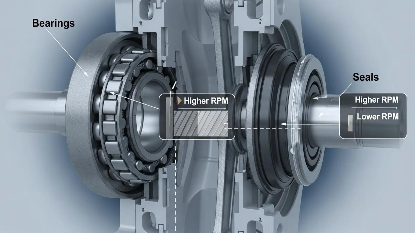
How Does Compressor RPM Affect Component Wear and Failure Modes?
The RPM of a compressor significantly impacts component wear and potential failure modes. Higher RPMs can lead to increased friction and heat generation, which accelerates wear on critical components such as bearings and seals. This heightened wear can result in vibration issues, which further exacerbate the risk of failure. Conversely, operating at lower RPMs may reduce wear but can also lead to inefficiencies and inadequate performance. Therefore, finding the right balance in RPM is essential for maintaining the integrity of compressor systems and ensuring reliable operation.
Research further supports that managing compressor speed is critical for mitigating friction and wear, thereby enhancing efficiency and operational longevity.
Industry research also supports the relationship between compressor speed, friction, and component wear:
Compressor RPM: Impact on Friction, Wear, and Efficiency
Different outlet pressures and revolution speeds on test compressor indicated power increase with rising discharge pressure and revolution speed. The reduction compressor speed from 1500 RPM to 1000 RPM would decrease the effects of friction to almost twice. It’s important to use coatings like TiN or WC/C, which have good and very good, wear resistance properties in order to reduce friction and wear on rotary vane friction pair.
Vane friction and wear influence on rotary vane compressor efficiency and operation: research and analysis review, 2017
When comparing real-world systems—such as LW Americas and BAUER Compressors—RPM design differences can significantly impact maintenance requirements, component wear, and long-term system performance. For a detailed comparison, see our LW Americas vs Bauer compressors comparison.
What Are the Recommended Maintenance Intervals Based on Compressor RPM?
Maintenance intervals vary based on compressor design, operating conditions, and manufacturer recommendations. The following examples illustrate how maintenance frequency may differ based on RPM, but actual service intervals should always follow manufacturer guidelines.
High RPM Compressors: Maintenance every 1,000 hours of operation or every three months, whichever comes first.
Medium RPM Compressors: Maintenance every 2,000 hours or every six months.
Low RPM Compressors: Maintenance every 3,000 hours or annually.
Environmental factors, such as operating conditions and load variations, should also be considered when determining maintenance schedules.
RPM Category
Maintenance Interval
Recommended Practices
High RPM
Every 1,000 hours
Frequent inspections and lubrication
Medium RPM
Every 2,000 hours
Regular checks on seals and bearings
Low RPM
Every 3,000 hours
Annual comprehensive maintenance
This table illustrates how maintenance intervals vary based on compressor RPM, emphasizing the need for tailored maintenance strategies. Note: These intervals are illustrative examples only and may vary significantly depending on compressor type, usage, and manufacturer specifications.
How Can Optimizing Compressor RPM Extend Equipment Lifespan?
Optimizing compressor RPM can significantly extend the lifespan of equipment by reducing maintenance frequency and minimizing component wear. By operating at the optimal RPM, operators can achieve a balance between performance and longevity. This optimization leads to several benefits:
Reduced Maintenance Frequency: Lower wear rates result in less frequent maintenance, saving time and costs.
Minimized Component Wear: Operating within the ideal RPM range decreases the stress on components, prolonging their life.
Enhanced Efficiency: Optimized RPM improves energy efficiency, leading to lower operational costs.
Techniques for RPM Control to Reduce Wear and Failure
Controlling RPM effectively is essential for reducing wear and preventing failures in compressor systems. Techniques for RPM control include:
Variable Frequency Drives (VFDs): These devices allow for precise control of motor speed, enabling operators to adjust RPM based on demand.
Regular Monitoring: Implementing monitoring systems can help track RPM and identify deviations from optimal levels.
Scheduled Maintenance: Regular maintenance ensures that components are in good condition, reducing the likelihood of failures related to RPM fluctuations.
By employing these techniques, operators can maintain optimal RPM levels, thereby enhancing the reliability and lifespan of their compressor systems.
Case Studies Demonstrating Lifespan Improvements Through RPM Management
Several case studies highlight the benefits of effective RPM management in extending equipment lifespan. For instance, a manufacturing facility that implemented VFDs on its high RPM compressors reported a reduction in maintenance costs and an increase in equipment lifespan. Another case study in the HVAC industry demonstrated that optimizing RPM led to a decrease in component failures, significantly improving operational efficiency.
These examples illustrate the tangible benefits of managing compressor RPM effectively, reinforcing the importance of this parameter in maintenance strategies and equipment longevity.
Dive Blending Panels Explained: How to Set Up a Nitrox and Trimix Fill Station for Accurate Scuba Gas Mixing
Setting up a Nitrox and Trimix fill station is essential for divers who require specific gas mixtures for their underwater adventures. Understanding dive blending panels is crucial for achieving accurate gas mixing, ensuring safety, and optimizing performance. This article will guide you through the components, safety procedures, and best practices for establishing a reliable fill station. By the end, you will have a comprehensive understanding of how to set up a Nitrox fill station and the necessary steps for Trimix gas mixing. We will also explore the role of dive blending panels and the integration of oxygen analyzers in this process.
Accurate Scuba Gas Mixing
Accurate scuba gas mixing is vital for ensuring divers receive the correct gas mixtures for their specific needs. The partial pressure method is commonly used, which involves calculating the individual gas components based on their desired percentages. Utilizing certified gas blending panels is essential for achieving precise mixtures, as they are designed to handle the complexities of gas blending. Pressure gauges play a critical role in monitoring the gas pressures, ensuring that the mixtures remain within safe limits.
Further research emphasizes the importance of precise equipment and calibration in achieving the desired gas mixtures for both Nitrox and Trimix.
Nitrox & Trimix Blending Facility Setup
present in facilities for NITROX and TRIMIX manufacturing, is added inside during the filling process. Thus, accurate scales are crucial. This curves correlate the valve settings with the final mixture.
Continuous flow type gas blending facility used for autonomous and system diving, NI Alboiu, 2017
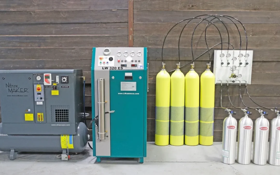
Essential Components
To set up a Nitrox and Trimix fill station, several essential components are required. These include:
Gas Blending Panels: The core of the system, responsible for mixing gases accurately.
Oxygen Analyzers: Used to verify the gas mixtures and ensure they meet the required specifications.
Compressor Selection: A high-quality compressor is necessary to fill tanks efficiently and safely.
Each component plays a significant role in the overall functionality of the fill station, contributing to the safety and effectiveness of the gas blending process.
Safety Procedures
Implementing safety procedures is paramount when operating a Nitrox and Trimix fill station. Here are key protocols to follow:
Training Requirements: All personnel must be trained in gas blending operations and emergency procedures.
Monitoring Gas Mixtures: Regular checks of gas mixtures are essential to ensure accuracy and safety.
Emergency Procedures: Establish clear emergency protocols for handling gas leaks or equipment failures.
Following these safety procedures helps mitigate risks associated with gas blending and ensures a safe working environment.
Effective training is a cornerstone of these safety measures, ensuring that all personnel are proficient in gas blending techniques and safety protocols.
Dive Center Gas Blending Safety & Training
gas blending techniques to continually improve safety protocols that diving centres adopt to ensure the purity and quality of breathing gas. Training in gas blending is necessary for those blending the gases.
Breathing Gas Quality and Monitoring in Dive Centres of the Maltese Islands, 2024
LW Americas is a specialized provider of high-quality dive blending panels and related equipment designed for setting up Nitrox and Trimix fill stations. Their products are engineered to meet safety standards, ensuring reliable performance in gas blending operations.
Best Practices
Adhering to best practices in gas blending can enhance the efficiency and safety of your operations. Consider the following:
Gas Selection: Choose the appropriate gas mixtures based on dive profiles and requirements.
Quality Control: Regularly inspect and maintain equipment to ensure optimal performance.
User-Friendly Design: Opt for blending panels that are intuitive and easy to operate, reducing the likelihood of errors.
Implementing these best practices will contribute to a more effective and safer gas blending process.
What Are Dive Blending Panels and Their Role in Scuba Gas Blending?
Dive blending panels are specialized systems designed to mix gases accurately for scuba diving applications. They function by controlling the flow of different gases, allowing for precise adjustments to achieve the desired gas mixture. The importance of these panels lies in their ability to ensure that divers receive the correct gas mixtures, which is crucial for safety and performance underwater. Additionally, many modern blending panels come equipped with safety monitoring features that alert operators to any discrepancies in gas mixtures.
How Do Oxygen Analyzers Integrate with Dive Blending Panels?
Oxygen analyzers play a critical role in the gas blending process by verifying the accuracy of the gas mixtures produced by dive blending panels. These devices measure the percentage of oxygen in the gas mixture, ensuring it meets the required specifications for safe diving. The integration of oxygen analyzers with blending panels enhances the overall safety and reliability of the gas blending process, providing divers with confidence in their gas supplies.
Which Components Constitute a Nitrox and Trimix Blending System?
A Nitrox and Trimix blending system consists of several key components that work together to produce accurate gas mixtures. These components include:
Gas Inlets: Where the individual gases enter the blending system.
Pressure Gauges: Essential for monitoring the pressure of each gas component.
Control Valves: Used to regulate the flow of gases into the blending panel.
Understanding these components is crucial for anyone looking to set up a reliable gas blending system. LW Americas can help you with a setup for a yacht, which you can learn about more on the NitroxMaker Yacht Series information page.
How to Set Up a Nitrox Fill Station Using Dive Blending Panels?
Setting up a Nitrox fill station involves several steps to ensure proper functionality and safety. Here’s a step-by-step guide:
Install the Blending Panel: Position the dive blending panel in a well-ventilated area, ensuring easy access to gas inlets.
Connect the Oxygen Analyzer: Integrate the oxygen analyzer with the blending panel to monitor gas mixtures.
Calibrate the System: Follow the manufacturer’s instructions to calibrate the blending panel and oxygen analyzer for accurate readings.
Conduct Safety Checks: Before operation, perform thorough safety checks to ensure all components are functioning correctly.
By following these steps, you can establish a Nitrox fill station that meets safety and performance standards.
What Are the Step-by-Step Procedures for Nitrox Fill Station Setup?
The setup process for a Nitrox fill station can be broken down into detailed steps:
Gather Necessary Equipment: Ensure you have all required components, including the blending panel, oxygen analyzer, and compressor.
Assemble the System: Connect the blending panel to the gas inlets and ensure all connections are secure.
Test the System: Run a test cycle to verify that the blending panel and oxygen analyzer are functioning correctly.
Document Procedures: Keep a record of the setup process and any adjustments made for future reference.
These procedures will help ensure a smooth and efficient setup for your Nitrox fill station.
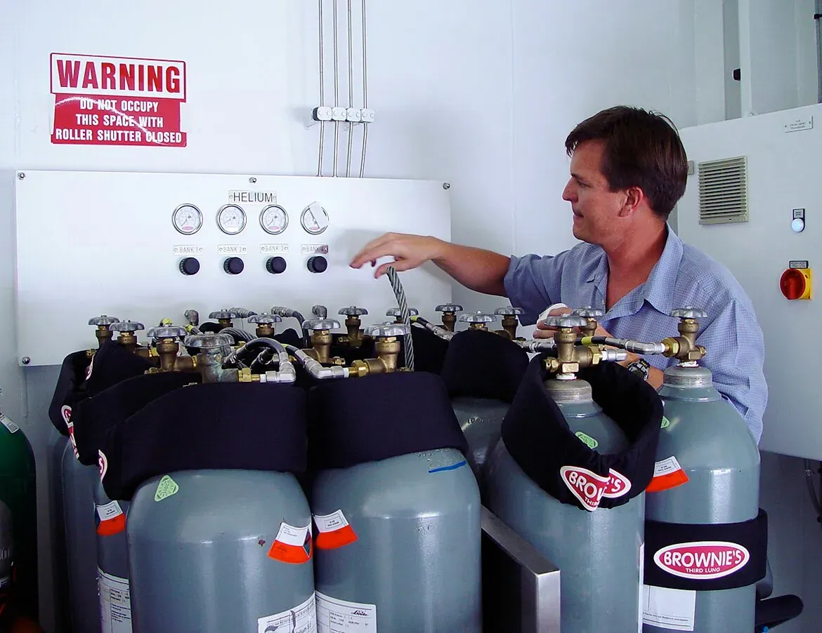
What Are the Procedures for Trimix Gas Mixing and Blending Setup?
Trimix gas mixing requires careful attention to detail to ensure safety and accuracy. The procedures include:
Determine Gas Ratios: Calculate the appropriate ratios of oxygen, helium, and nitrogen based on dive profiles.
Set Up the Blending Panel: Follow the same setup procedures as for Nitrox, ensuring all components are in place.
Monitor Gas Mixtures: Use the oxygen analyzer to verify that the gas mixtures meet the required specifications.
Conduct Final Checks: Before filling tanks, perform final checks to ensure all systems are functioning correctly.
By adhering to these procedures, you can achieve accurate Trimix gas blending for your diving needs.
What Safety Standards and Certification Requirements Govern Dive Blending Panels?
Safety standards and certification requirements are critical for ensuring the safe operation of dive blending panels. Key standards include:
CGA Compliance: Adherence to Compressed Gas Association standards for gas handling and safety.
TÜV Certification: Ensures that equipment meets international safety and quality standards.
ISO Standards: Compliance with ISO standards for quality management and safety in gas blending operations.
These certifications provide assurance that dive blending panels are designed and manufactured to meet stringent safety requirements.
Adhering to established industry guidelines, such as those from the Compressed Gas Association, is fundamental for ensuring the safety of Nitrox mixtures.
Nitrox Blending Safety Guidelines
society guidelines from ASTM, Compressed Gas Association, and The CGA pamphlet G-4.4 [1] states that any gas mixture that contains any mixture between 21 and 40 percent oxygen is safe to use.
Use of Oxygen-Enriched Mixtures in Recreational SCUBA Diving–Is the Public Being, 1997
Which Industry Certifications Ensure Compliance for Gas Blending Equipment?
Several industry certifications are essential for ensuring compliance in gas blending equipment:
CGA Grade E: Specifies the requirements for oxygen service equipment.
NFPA 1989: Covers the standards for respiratory protection equipment.
ISO 8573: Addresses the purity of compressed air and gases.
These certifications help maintain high safety and quality standards in gas blending operations.
How to Implement Safety Procedures for Gas Blending Operations?
Implementing safety procedures for gas blending operations involves several key steps:
Regular Maintenance: Schedule routine maintenance for all equipment to ensure optimal performance.
Monitoring Systems: Utilize monitoring systems to track gas mixtures and detect any anomalies.
Documentation: Keep detailed records of all safety checks and maintenance performed on the equipment.
By following these procedures, you can enhance the safety and reliability of your gas blending operations. If you need additional help, contact LW Americas support team.
How to Choose the Right Compressor for Dive Tanks: Comprehensive Guide to Dive Tank Air Compressors and Equipment Selection
Selecting the right compressor for dive tanks is crucial for ensuring operational safety and efficiency in diving operations. A well-chosen compressor not only meets the specific air quality and pressure requirements but also supports reliable and consistent tank filling processes. This comprehensive guide will delve into the essential factors to consider when choosing a compressor, including pressure requirements, tank size, intended use, and air quality standards. Many divers and dive shop owners face challenges in selecting the appropriate equipment that aligns with their operational needs. By understanding the key elements of compressor selection, you can make informed decisions that optimize safety and performance. This article will cover the critical factors for selecting dive tank air compressors, essential equipment considerations, best practices for maintaining operational reliability, and the types of compressors suitable for dive tanks.
Comprehensive Guide to Choosing the Right Compressor for Dive Tanks
Choosing the right compressor for dive tanks is a vital decision that impacts both safety and operational efficiency. The compressor must be capable of delivering the required pressure and air quality to support safe diving practices. Understanding the various factors involved in compressor selection can help divers and dive shop owners make informed choices. This guide will explore the key considerations that should influence your decision-making process, ensuring that you select a compressor that meets your specific operational requirements.
Key Factors for Selecting Dive Tank Air Compressors
When selecting a dive tank air compressor, several key factors must be considered to ensure reliable performance and safety. These factors include pressure requirements, tank size and capacity, intended use, air quality standards, environmental conditions, power source, filtration and purification, monitoring and controls, and maintenance and support. To better understand the options and features, we recommend reviewing this article which discusses the various high pressure compressor types used by divers.
Pressure Requirements
Understanding the required fill pressures for dive tanks is essential for selecting the right compressor. Different diving activities necessitate varying pressure levels, typically ranging from 2,500 to 3,500 psi for recreational diving. Compressors must be capable of meeting these pressures consistently to support safe diving operations. Additionally, it is crucial to consider the compressor’s capabilities to handle multiple fills, especially for dive shops that cater to numerous customers.
Tank Size and Capacity
Assessing tank sizes and flow rates is another critical factor in compressor selection. The flow rate of a compressor must align with the size of the tanks being filled. For instance, larger tanks require compressors with higher flow rates to ensure efficient filling. Understanding the operational demands of your diving activities will help you choose a compressor that can handle the required workload without compromising reliability.
Intended Use
Identifying the intended use for the compressor is vital in determining the appropriate model. Recreational divers may prioritize portability, while commercial operations might require stationary compressors for high-volume filling. Understanding these distinctions will guide you in selecting a compressor that best fits your specific operational needs.
Air Quality Standards
Ensuring compliance with air quality standards is paramount for supporting safe diving practices. The Compressed Gas Association (CGA) Grade E and EN 12021 standards outline the necessary air quality requirements for breathing air. Selecting a compressor that supports compliance with these standards when properly maintained and operated is essential for the safety of divers, as it helps ensure that the air supplied meets recognized breathing air quality criteria.
Environmental Conditions
Considering the operational environment is crucial when selecting a compressor. Factors such as site constraints, temperature variations, and humidity levels can impact compressor performance. For instance, compressors used in harsh environments may require additional protective features to ensure longevity and reliability.
Power Source
Matching power requirements with available sources is another important consideration. Compressors can be powered by electricity, gasoline, or diesel, and understanding the compatibility with your power source is essential for seamless operation. Additionally, energy efficiency should be a priority to minimize operational costs.
Filtration and Purification
Selecting compressors with adequate filtration systems is vital for supporting compliance with air quality standards. The type of filtration system used can significantly impact the purity of the air supplied to divers. Multi-stage filtration systems are often recommended to help meet recognized breathing air standards such as CGA Grade E or EN 12021 when properly maintained and operated, thereby reducing the risk of contaminants.
Monitoring and Controls
The importance of monitoring air quality parameters cannot be overstated. Advanced monitoring systems can provide real-time data on air quality, supporting compliance with safety standards. Regular sampling and monitoring help maintain the integrity of the air supplied to divers, contributing to safer diving operations.
Maintenance and Support
Considering maintenance needs and support availability is essential for ensuring the longevity and reliable operation of your compressor. Routine maintenance schedules should be established to keep the compressor in optimal working condition. Additionally, reliable customer support from the manufacturer can provide peace of mind in case of any operational issues.
Essential Equipment Considerations
When selecting a compressor, several essential equipment considerations must be taken into account. These include the type of compressor, necessary accessories, and performance optimization features.
Compressor Type
Different types of compressors are available for dive tank applications, including high-pressure piston compressors and rotary screw compressors. Each type has its advantages and disadvantages, making it essential to evaluate which model best suits your needs. For instance, high-pressure piston compressors are known for their reliability and ability to achieve high pressures, while rotary screw compressors offer continuous operation and energy efficiency.
Accessories
Essential accessories for compressor functionality can enhance performance and safety. Items such as air inlet silencers, boost pumps, and purification systems should be considered when selecting a compressor. These accessories can improve the overall efficiency and effectiveness of the compressor, ensuring that it meets the demands of your diving operations.
Best Practices for Maintaining Operational Reliability
To maintain reliable operation of your dive tank compressor, several best practices should be followed. These include regular maintenance, air quality monitoring, proper storage conditions, operator training, and consulting experts when necessary.
Regular Maintenance
Routine maintenance is crucial for ensuring the longevity and reliability of your compressor. Regular checks, filter replacements, and oil level monitoring should be part of your maintenance schedule. Establishing a proactive maintenance routine can prevent unexpected breakdowns and ensure consistent compressor performance.
Air Quality Monitoring
Monitoring air quality is essential for supporting safe diving operations. Regular testing and compliance with established standards can help prevent contamination and support that the air supplied meets recognized breathing air quality criteria. Implementing a robust air quality monitoring system can provide operational assurance during dives.
Storage and Environment
Proper storage conditions for compressors can significantly impact their performance and lifespan. Compressors should be stored in clean, dry environments to prevent damage from moisture and contaminants. Ensuring that the storage area is well-ventilated can also help maintain optimal operating conditions.
Training and Knowledge
Training operators for safe use of compressors is vital for ensuring safety during diving operations. Providing comprehensive training programs can enhance operator knowledge and efficiency, reducing the risk of accidents and improving overall operational reliability.
Consult Experts
When in doubt, consulting experts can provide valuable insights into compressor selection and maintenance. Engaging with manufacturers and industry professionals can help you make informed decisions that align with your operational needs.
Types of Compressors Suitable for Dive Tanks
Several types of compressors are suitable for dive tanks, each offering unique advantages. Understanding these options can help you select the best compressor for your specific needs.
Reciprocating Compressors: These compressors are known for their reliability and ability to produce high pressures, making them suitable for filling dive tanks.
Rotary Screw Compressors: Offering continuous operation and efficiency, rotary screw compressors are ideal for commercial applications where high volume is required.
Portable Compressors: These compressors provide mobility and flexibility, making them suitable for recreational divers who need to fill tanks on the go.
Compressor Technologies That Meet Dive Tank Requirements
When evaluating compressor technologies, it is essential to consider their suitability for dive tank applications. Technologies such as oil-free compressors, piston compressors, and rotary screw compressors each have unique characteristics that can impact performance and operational safety.
Comparison of Oil-Free, Piston, and Rotary Screw Compressors
Comparing oil-free, piston, and rotary screw compressors reveals distinct advantages and disadvantages for each type. Oil-free compressors are often preferred for their ability to provide clean air without the risk of oil contamination. Piston compressors are known for their high-pressure capabilities, while rotary screw compressors excel in continuous operation and energy efficiency.
Air Quality and Filtration Standards for Dive Tank Compressors
Understanding air quality and filtration standards is crucial for supporting safe diving practices. The CGA Grade E and EN 12021 standards outline the necessary requirements for breathing air, emphasizing the importance of proper filtration systems to maintain air purity. Selecting filtration systems that support compliance with these standards when properly maintained and operated is essential for reducing the risk of contaminants.
Air Filtration Systems That Support Safe Scuba Tank Filling
Selecting the right air filtration system is essential for supporting safe scuba tank filling. Multi-stage filtration systems are recommended to effectively reduce contaminants and support compliance with recognized air quality standards.
Certifications and Safety Standards Applicable to Dive Tank Compressors
Several certifications and safety standards apply to dive tank compressors, including CGA Grade E, EN 12021, and ISO 8573-1. Understanding these standards is vital for ensuring that the compressor supports safety and performance requirements.
Determining Compressor Compatibility with Different Dive Tank Types
Determining compressor compatibility with different dive tank types involves understanding the specific requirements of each tank. Compatibility charts can provide valuable insights into pressure ratings and flow rates, ensuring that the selected compressor meets the necessary specifications.
Factors Affecting Compressor Compatibility with Aluminum and Steel Tanks
Factors influencing compressor compatibility with aluminum and steel tanks include material differences, pressure ratings, and usage scenarios. Understanding these factors can help ensure that the compressor selected is suitable for the specific tank type.
Using Compatibility Charts for Equipment Selection
Using compatibility charts effectively involves identifying tank types, consulting manufacturer charts, and interpreting pressure and flow data. This process can help ensure that the selected compressor is compatible with the dive tanks being used.
Best Practices for Compressor Maintenance for Dive Tanks
Implementing best practices for compressor maintenance is essential for supporting operational safety and equipment longevity. Regular checks, filter replacements, and air quality testing should be part of a comprehensive maintenance routine.
Recommended Service Intervals for Dive Tank Compressors
Dive tank compressors should be serviced regularly to maintain optimal performance. Recommended service intervals may vary based on usage, but routine maintenance should include filter changes, oil changes, and full overhauls as needed.
Maintenance Procedures to Ensure Operational Safety and Longevity
Establishing maintenance procedures that focus on routine inspections, documentation, and troubleshooting tips can help ensure operational safety and longevity. Keeping detailed records of maintenance activities can also aid in identifying potential issues before they become significant problems.
Choosing Between Portable and Stationary High-Pressure Air Compressors
Choosing between portable and stationary high-pressure air compressors involves evaluating mobility versus capacity. Portable compressors offer flexibility for recreational divers, while stationary compressors are preferable for dive shops requiring consistent high volume. For a deeper understanding prior to choosing between a portable or stationary compressor, review our article discussing the advantages of portable high pressure dive compressors.
Advantages of Portable Scuba Compressors
Portable scuba compressors provide several advantages, including mobility, situational support, and operational independence. These features make them ideal for divers who need to fill tanks in various locations.
For example, a Navy evaluation demonstrates real-world performance validation of portable high-pressure compressors in demanding operational environments.
When Stationary Compressors Are Preferable for Dive Tank Filling
Stationary compressors are preferable for dive tank filling when consistent high volume is required. Their robust construction and energy efficiency make them suitable for commercial applications where reliability is essential.
Key Considerations When Purchasing Scuba Tank Filling Equipment
When purchasing scuba tank filling equipment, several key considerations should be taken into account. These include performance specifications, safety features, and technological innovations that can influence your decision.
Product Features That Optimize Performance and Safety
Optimizing performance and safety in scuba tank filling equipment involves selecting features such as compressor type, filtration systems, and user-friendly controls. These elements can significantly impact the overall efficiency and operational safety of the compressor.
Evaluating Compressor Specifications Such as Flow Rate and Maximum Pressure
Advantages of Portable High Pressure Dive Compressors: Comprehensive Insights for Diving Professionals and Enthusiasts
Portable high pressure dive compressors are essential tools for divers, providing a reliable source of compressed air for underwater exploration. These compressors are designed to be compact and efficient, making them ideal for both recreational and professional diving applications. In this article, we will explore the numerous advantages of using portable high pressure dive compressors, including their efficiency, portability, and advanced filtration systems. Additionally, we will discuss how these compressors serve outdoor sports enthusiasts and professional divers, highlighting their practical applications in various scenarios. By understanding the benefits and features of these compressors, divers can make informed decisions that enhance their diving experiences. For a more detailed review of compressor options, check out our complete guide on high pressure compressors for diving systems.
The specialized design of these compressors, often featuring multiple cylinders, allows them to achieve the high pressures necessary for critical applications like scuba tank filling and breathing air systems.
Portable High-Pressure Compressors for Breathing Air Systems
These compressors use two cylinders to further increase the pressure of the air, making them useful for applications that require high-pressure breathing air, such as scuba tank filling and commercial diving breathing air systems.
FABRICATION AND TESTING OF A PORTABLE BREATHING EQUIPMENT FOR LOW PRESSURE CONDITIONS, 2023
What Are the Core Benefits of Using Portable High Pressure Dive Compressors?
Portable high pressure dive compressors offer several key benefits that make them indispensable for divers. These advantages include efficiency in filling tanks, portability for remote locations, and cost-effectiveness in operations. By utilizing these compressors, divers can ensure they have a reliable air supply, which is crucial for safety and performance underwater.
How Does Portability Enhance Dive Compressor Utility?
The portability of dive compressors significantly enhances their utility, especially in remote diving operations and emergency response situations. Divers can easily transport these compressors to various locations, allowing them to fill tanks on-site without the need for a stationary air supply. This flexibility is particularly beneficial for expeditions to remote areas where access to traditional filling stations may be limited.
In What Ways Do Compact Designs Improve Operational Efficiency?
Compact designs of portable dive compressors contribute to operational efficiency by allowing for high performance despite their size. These compressors are engineered to deliver powerful output while consuming less energy, making them an environmentally friendly choice. Their small footprint also means they can be easily stored and transported, further enhancing their practicality for divers. For additional information, you can review the different high compressor types for divers here.
How Do Portable High Pressure Dive Compressors Serve Outdoor Sports Enthusiasts and Professional Divers?
Portable high pressure dive compressors are not only beneficial for recreational divers but also serve outdoor sports enthusiasts and professional divers effectively. Their mobility allows for logistical independence, enabling divers to engage in various activities without being tethered to a fixed air supply.
What Use Cases Highlight the Advantages for Recreational Diving?
Recreational diving often takes place in remote locations, where access to air filling stations can be challenging. Portable dive compressors allow divers to fill their tanks on-site, ensuring they have the necessary air supply for their adventures. This capability is particularly advantageous for training and instruction scenarios, where multiple divers may require air fills in a short period.
What Are the Comparative Advantages of LW Americas’ Portable Dive Compressors?
LW Americas specializes in providing portable high pressure dive compressors that stand out in the market due to their unique features. These compressors are designed with advanced filtration systems that support compliance with recognized air quality standards such as CGA Grade E and EN 12021, which are critical for diving safety.
Ensuring the purity of breathing air is paramount for diver safety, a concern that has driven the development of rigorous testing protocols and the demand for advanced monitoring solutions.
Real-time Air Quality Monitoring for Diving Compressors
The U.S. Navy Divers Air Sampling Program coordinates the mandatory semiannual air purity testing of compressors used to supply divers air in the Fleet. Gas sampling kits are sent to the field, where gas samples are taken. These samples are then returned to a contract laboratory for analysis, with the results subsequently reported back to the field. This approach is expensive, cumbersome, and potentially unreliable. Consequently, the U.S. Navy is interested in having a real-time online air quality monitor to ensure that compressors deliver safe diving air.
Development and Evaluation of an Online Air Quality Monitor (Diveair2) for Diving Compressors, 2009
How Do LW Americas Compressors Differ in Portability and Filtration?
LW Americas’ portable dive compressors are engineered for superior portability and filtration compared to traditional models. Their lightweight design allows for easy transport, while the advanced filtration systems help remove contaminants from the air, supporting compliance with industry air quality standards to help ensure divers breathe clean air during their dives.
What Industry Standards and Certifications Validate LW Americas’ Product Quality?
LW Americas’ products are built to meet stringent industry standards and certifications, which validate their quality and reliability. These certifications ensure that divers can trust the performance of their compressors, providing peace of mind during underwater excursions.
Efficiency and Cost-Effectiveness
The efficiency and cost-effectiveness of portable high pressure dive compressors are significant factors that contribute to their popularity among divers. These compressors are designed to maximize performance while minimizing operational costs, making them an attractive option for both recreational and professional use.
Real-world evaluations of portable compressors demonstrate their efficiency in action, showcasing impressive tank filling times and economical operation.
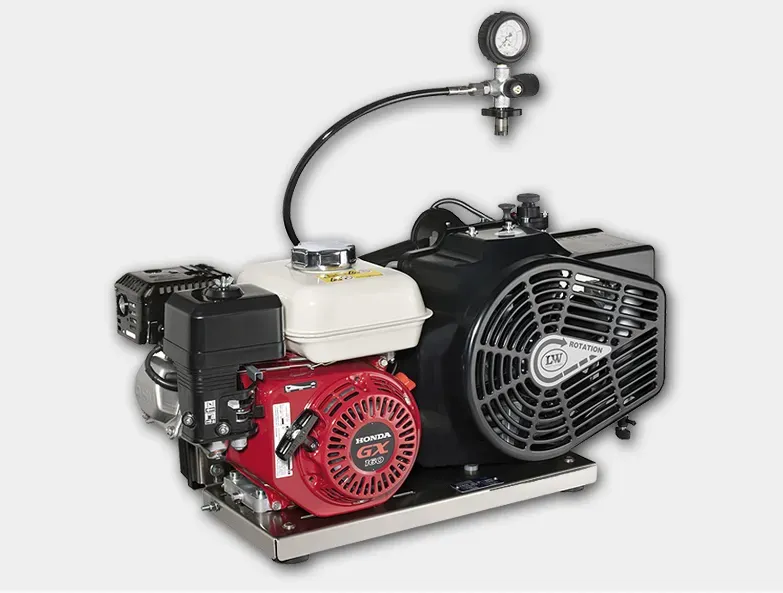
A gasoline engine driven high-pressure breathing air compressor, BAUER Varius G-3, was evaluated by the Navy Experimental Diving Unit to determine its suitability for Navy use. Results of the 50-hour test showed that the portable compressor delivers breathing air at an average charge rate of 2.07 CFM, charging twin 72 cu. ft., twin 50 cu. ft., and single 80 cu. ft. scuba tanks in 71, 44, and 39 minutes respectively. The unit is easily maintained, sturdily constructed, and economical in gasoline fuel consumption.
Test and Evaluation of Bauer Portable High-Pressure Breathing Air Compressor, Model Varius G-3., 1980
Feature
Description
Benefit
Energy Efficiency
Utilizes advanced technology to reduce power consumption
Lowers operational costs
Compact Design
Small footprint for easy transport and storage
Enhances mobility for divers
High Output
Delivers powerful air compression
Ensures quick tank fills
This table illustrates how the features of portable dive compressors translate into tangible benefits for users, highlighting their efficiency and cost-effectiveness. To help make a decision, you can review our article on how to choose the right compressor for dive tanks.
Maintenance Practices to Ensure Optimal Performance of Portable High Pressure Dive Compressors
Proper maintenance is crucial for ensuring the optimal performance of portable high pressure dive compressors. Regular maintenance practices can extend the lifespan of these compressors and enhance their reliability during use.
What Are the Recommended Maintenance Intervals and Procedures?
It is recommended that divers perform routine checks on their compressors, including inspecting filters, checking for leaks, and ensuring that all components are functioning correctly. Regular maintenance intervals should be established based on usage frequency, with more frequent checks for compressors used in demanding environments.
How Does Proper Maintenance Extend Compressor Lifespan and Reliability?
By adhering to recommended maintenance practices, divers can significantly extend the lifespan and reliability of their portable dive compressors. Regular upkeep not only prevents potential issues but also ensures that the compressors operate at peak efficiency, providing divers with the air supply they need for safe and enjoyable diving experiences.
For a broader understanding of high-pressure diving compressors and their applications, readers are encouraged to explore our comprehensive guide on high-pressure diving compressors, which covers a wide range of topics to support informed decision-making.