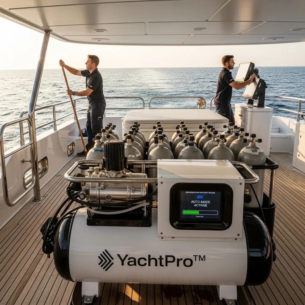
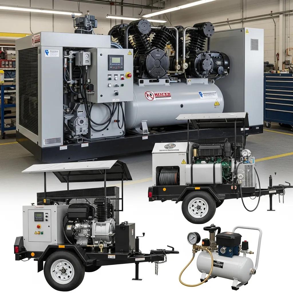
Custom High-Pressure Compressors for Yacht Operations: Optimizing Marine Air Systems for Superyachts
Custom high-pressure compressors play a crucial role in yacht operations, particularly in ensuring the availability of clean, breathable air for various applications. These specialized compressors are designed to meet the unique demands of marine environments, providing essential support for activities such as filling scuba tanks and maintaining onboard breathing air systems. In this article, we will explore the importance of custom yacht air compressors, their core applications, and how they enhance safety and efficiency on superyachts. Additionally, we will discuss the YachtPro™ series from LW Americas, which offers advanced features tailored for yacht operations, and best practices for maintenance and support of these critical systems.
What Are Custom Yacht Air Compressors and Why Are They Essential?
Custom yacht air compressors are specialized high-pressure air compressors designed for use in marine environments, particularly on yachts. They are essential for providing clean, breathable air for various applications, including filling scuba tanks and supporting onboard breathing air systems. These compressors typically incorporate advanced filtration and monitoring systems to ensure air quality meets safety standards, which, when properly specified, installed, and maintained, can meet stringent safety standards like NFPA 1989. This is crucial for maintaining the health and safety of individuals using the air, especially in emergency situations or during recreational activities.
Key Benefits of Bespoke Marine Air Solutions for Superyachts
Bespoke marine air solutions offer several key benefits for superyachts:
Customization: Tailored solutions ensure that the compressor meets the specific needs of the yacht, enhancing operational efficiency.
Safety Compliance: Advanced filtration systems, when properly specified, installed, and maintained, ensure that the air quality meets stringent safety standards, protecting crew and passengers.
Operational Efficiency: Custom compressors are designed for continuous-duty operation, which, when properly specified, installed, and maintained, minimizes downtime and maintenance needs.
These benefits highlight the importance of investing in high-quality, custom yacht air compressors to ensure optimal performance and safety.
How Does the YachtPro™ Series Meet Superyacht Compressor Needs?
The YachtPro™ Series meets superyacht compressor needs by providing fully automated systems like the YP100, which allows users to connect their tanks, open the valves, and turn the system on, freeing them to attend to other duties while the tanks fill to the programmed pressure. The compressor automatically stops when the tanks are full, enhancing convenience and efficiency. Additionally, it includes a Variable Frequency Drive (VFD) to manage the inrush current during motor startup, ensuring smoother operation.
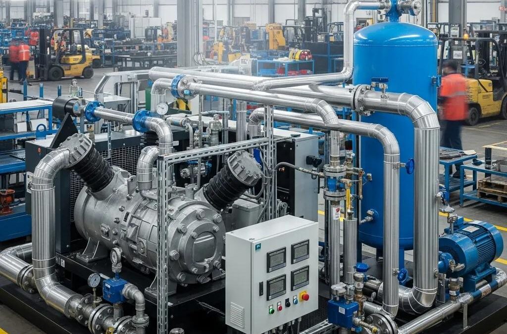
Continuous-Duty Operation and Robust Construction Features
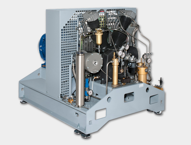
Continuous-duty operation and robust construction features are emphasized in the context of compressor design. Continuous-duty platforms incorporate durable mechanical components and advanced cooling strategies, such as improved head designs and one-piece cast blocks, to support long run times and predictable maintenance intervals when properly specified and maintained. These features enable compressors to operate efficiently under continuous demand while minimizing thermal stress. Additionally, energy-efficient designs, like variable-speed drives, contribute to lower operating costs and enhance the resilience of critical systems, such as breathing-air applications, when integrated and maintained correctly.
Lower RPM Design for Noise Reduction and Durability
The lower RPM design of the YachtPro™ series significantly reduces noise levels, enhancing the onboard experience for crew and guests. This design not only minimizes operational noise but also contributes to the durability of the compressor, as lower RPMs reduce wear and tear on mechanical components. This combination of noise reduction and increased longevity makes the YachtPro™ series an ideal choice for luxury vessels where comfort and reliability are paramount.
What Are the Core Applications of Marine Breathing Air Compressors on Yachts?
The core applications of marine breathing air compressors on yachts include:
Filling SCBA Cylinders: Compressing ambient air to high pressure, filtering contaminants, and storing the compressed air for safe filling of SCBA cylinders.
Ensuring Air Quality: Utilizing multi-stage purification systems to capture particulates, hydrocarbons, and moisture, ensuring the air meets health and safety criteria.
Supporting Safety and Readiness: Providing on-site access to breathing air, which enhances crew readiness and reduces response delays during emergencies or training.
Monitoring Air Quality: Integrating continuous monitoring systems to detect potential contaminants and ensure compliance with relevant standards, such as NFPA 1989, when applicable and properly configured.
These applications are essential for maintaining safety and operational efficiency on yachts.
SCUBA Tank Filling Solutions and Breathing Air Supply Systems
For yacht operations, SCUBA tank filling solutions and breathing air supply systems are critical. These systems require integrated design to match compressor capacity, storage, and downstream purification, ensuring a reliable supply of high-pressure, purified air for various marine activities.
Emergency and Safety Air Systems Integration
Marine breathing air compressors are integral to emergency and safety air systems on yachts. They provide immediate access to breathable air in critical situations, ensuring that crew members can respond effectively to emergencies. The integration of these systems with onboard safety protocols enhances overall readiness and safety, making them indispensable for luxury vessels.
How Can Custom Marine Compressor Installation and Design Enhance Yacht Operations?
Custom marine compressor installation and design can significantly enhance yacht operations by ensuring that the systems are tailored to the specific needs of the vessel. This includes optimizing the layout for space efficiency and ease of access for maintenance.
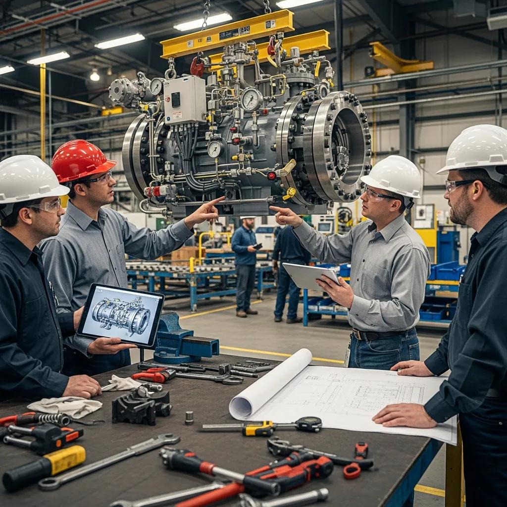
Project Management and 2D/3D Design Services for Tailored Solutions
Effective project management and advanced design services, including 2D and 3D modeling, allow for precise planning and execution of compressor installations. This tailored approach ensures that all components fit seamlessly within the yacht’s existing systems, maximizing efficiency and performance.
Case Studies of YachtPro™ Installations on Luxury Vessels
Several luxury vessels have successfully integrated the YachtPro™ series, showcasing its effectiveness in enhancing onboard air systems. These case studies demonstrate the positive impact of custom installations on operational efficiency and crew safety, providing valuable insights for future projects.
What Are Best Practices for Maintenance and Support of Yacht High-Pressure Compressors?
Maintaining high-pressure compressors is crucial for ensuring their longevity and reliability. Implementing best practices for maintenance can prevent costly downtime and ensure optimal performance.
Preventative Maintenance Schedules and Spare Parts Availability
Establishing a preventative maintenance schedule is essential for keeping compressors in peak condition when properly implemented. Regular inspections and timely replacement of worn components can significantly extend the lifespan of the equipment. Additionally, ensuring the availability of spare parts minimizes downtime during repairs.
North American Responsive Support and Service Guidance
LW Americas offers responsive support and service guidance for yacht operators, ensuring that any issues with high-pressure compressors are addressed promptly. This level of support is vital for maintaining operational efficiency and safety on luxury vessels.
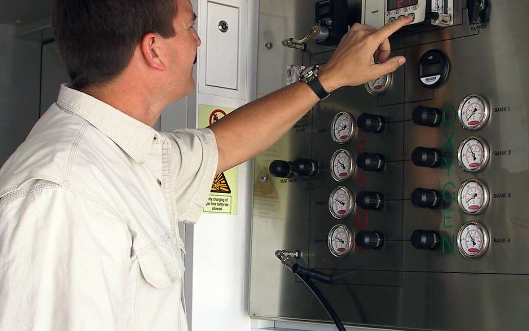
How Is Air Quality Ensured in Superyacht Breathing Air Systems?
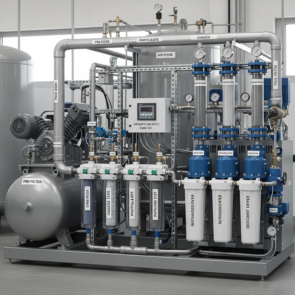
Air quality in superyacht breathing air systems is ensured through controlled pressure, certified filtration, and adherence to recognized standards for air quality when properly specified, installed, and maintained. This includes specifications for total hydrocarbons, carbon monoxide, moisture, and particulate limits. Essential components of the system include a staged filter train (pre-filter, coalescing oil remover, activated carbon or catalyst for hydrocarbons, and molecular sieve for moisture), along with continuous monitoring for carbon monoxide and carbon dioxide. These elements work together to capture contaminants and provide alerts to maintain compliance with air quality standards.
Advanced Purification Technologies and Monitoring Standards
Advanced purification technologies are critical for ensuring the safety and quality of breathing air on superyachts when properly implemented and maintained. These systems utilize multi-stage filtration processes to remove harmful contaminants, ensuring that the air supplied to crew and passengers is safe and compliant with health standards.
Compliance with Marine Air Quality Regulations and Safety Standards
Compliance with marine air quality regulations and safety standards is essential for yacht operations when systems are properly specified, installed, and maintained. Adhering to these regulations not only ensures the safety of individuals onboard but also protects the integrity of the marine environment. Regular audits and monitoring help maintain compliance and identify areas for improvement.
Component
Function
Importance
Pre-filter
Removes large particulates
Protects downstream filters
Coalescing oil remover
Eliminates oil aerosols
Ensures air purity
Activated carbon
Absorbs hydrocarbons
Maintains air quality
Different optimization strategies deliver distinct benefits through specific mechanisms.
Breathing Air Quality Standards: Understanding CGA G-7.1, ISO 8573-1, and Compliance Testing for Safe Air
Breathing air quality standards define the allowable contaminant levels in compressed air used for respiration, and they provide the technical specifications that support user safety across industrial, emergency response, diving, and medical settings. These standards work by specifying numeric limits for oxygen, carbon monoxide, carbon dioxide, hydrocarbons, water (dew point), and odor, and by prescribing testing and monitoring strategies that verify compliance. Understanding CGA G-7.1 and ISO 8573-1 helps operations choose proper filtration, monitoring, and compressor systems to minimize health risks and regulatory exposure. It’s crucial to recognize that while both are vital for air quality, CGA G-7.1 specifically addresses breathing air contaminant limits for human respiration, whereas ISO 8573-1 classifies general compressed air purity for industrial applications, focusing on particles, water, and oil. They are not interchangeable but often used in conjunction to ensure comprehensive air quality. This article explains the core requirements of CGA G-7.1, interprets ISO 8573-1 purity codes, outlines essential compliance testing practices, and details compressor design features that support sustained breathing air quality. Readers will get practical tables comparing grade limits, step-by-step ISO code interpretation, testing frequency guidance, and equipment feature checklists. Where relevant, the article notes how specialized providers — for example LW Americas with continuous-duty high-pressure compressors and breathing air purification and monitoring solutions — can support specification, testing workflows, and system integration without distracting from the standards-focused guidance.
What Are the Key Requirements of CGA G-7.1 for Breathing Air?
CGA G-7.1 is a technical standard that defines contaminant limits and grading for compressed breathing air, enabling consistent safety thresholds across industries. The standard lists specific maximum concentrations for oxygen, carbon monoxide (CO), carbon dioxide (CO2), total hydrocarbons, particulate matter, and dew point, and it sets odor acceptability criteria to ensure air is safe and comfortable to breathe. By defining grades such as Grade D, E, and L, G-7.1 links contaminant limits to intended applications—SCBA filling, diving fills, or specialized medical uses—and so informs filtration and monitoring requirements. The result of applying G-7.1 is a measurable specification that operations can verify through testing and continuous monitoring to reduce acute toxicity and chronic exposure risks. Understanding these numerical limits directly guides equipment choices, maintenance schedules, and recordkeeping practices that preserve compliance and user safety.
Grade
Primary contaminants limited
Typical limit highlights
Grade D
CO, CO2, hydrocarbons, dew point, O2
CO low ppm-level limit; dew point below specified threshold; O2 within safe percent range
Grade E
Stricter control for diving
Tighter hydrocarbon and CO limits tailored for breathing mixes and cylinder fills
Grade L
Specialized low-contaminant uses
Lower hydrocarbon and particulate allowances for medical or sensitive applications
This table lets engineers and safety managers match grades to filtration stacks, monitoring devices, and verification sampling protocols so systems achieve the intended Grade reliability.
What Defines CGA G-7.1 Grade D Air Specifications?
Grade D air under CGA G-7.1 is the common baseline for many occupational breathing-air applications because it balances achievable purification with protective limits for oxygen and common contaminants. Grade D specifies acceptable oxygen concentration ranges and maximum parts-per-million (ppm) limits for carbon monoxide and hydrocarbons, plus dew point ceilings to manage water content. Verification of Grade D typically requires on-site instrument readings for CO and dew point and laboratory or calibrated analyzer checks for hydrocarbons and particulates; recordkeeping should demonstrate periodic testing and corrective actions when values deviate. Operationally, Grade D is widely used for SCBA cylinder fills, workplace breathing air, and many industrial tasks where portable respiratory protection is required. Ensuring Grade D compliance focuses engineers on selecting multistage filtration, CO monitoring, and regular maintenance to prevent compressor or intake contamination.
This interpretation clarifies what system components and monitoring are necessary to reliably deliver Grade D air and prepares readers for contrasting Grades E and L.
How Do CGA G-7.1 Grades E and L Differ in Applications?
Grades E and L in CGA G-7.1 represent specialized use cases where different contaminant tolerances or applications demand adjusted specifications. Grade E is commonly associated with diving fills and gas blending (e.g., Nitrox) where hydrocarbon and CO limits are tighter to protect divers and to prevent mix degradation, while Grade L targets uses requiring very low hydrocarbons and particulates such as certain medical or laboratory breathing systems. Choosing between Grades E and L versus Grade D depends on exposure routes, vulnerability of users, and downstream gas processing steps; tighter grades often require additional activated carbon beds, catalytic CO removal, or finer coalescing and particulate filters. Equipment selection and certification should align with the chosen grade to avoid under- or over-specifying treatment stages.
Understanding these distinctions informs the filtration stack and monitoring priorities needed for each application and helps determine testing frequency and documentation intensity.
How Does ISO 8573-1 Classify Compressed Air Purity?
ISO 8573-1 is an internationally used standard that classifies general compressed air purity by three principal components: particles, water (expressed as dew point or liquid water), and oil (liquid and vapor). Unlike breathing air standards such as CGA G-7.1, ISO 8573-1 does not specify limits for gaseous contaminants like carbon monoxide or carbon dioxide, nor does it directly address human respiratory safety. Instead, it uses a three-number code—particle class.water class.oil class—so a specification like succinctly communicates the required maximum particle size/count, allowable dew point or water content, and permitted oil content. This structure makes ISO 8573-1 especially useful for specifying air for different downstream industrial uses because engineers can match a code to filtration, dryers, and coalescing or adsorption stages when designing systems. For breathing air applications, ISO 8573-1 purity classes are often used in conjunction with breathing air standards to ensure both mechanical system integrity and human safety.
Particles: Defines maximum particle size and count per cubic meter requiring physical filtration and fine coalescers.
Water: Specifies dew point or liquid water limits, guiding the use of refrigerated or desiccant dryers.
Oil: Indicates allowable oil aerosol and vapor concentration, informing adsorption media like activated carbon.
This interpretation bridges ISO class selection with practical component choices so teams can translate a purity code into concrete hardware and monitoring needs.
What Are the Particle, Water, and Oil Purity Classes in ISO 8573-1?
Particle, water, and oil classes in ISO 8573-1 each use class numbers where lower numbers represent cleaner air. Particle classes range from coarse to extremely fine particle counts, water classes control dew point or water content, and oil classes limit total oil content in mg/m³. Typical breathing-air targets often sit in low-number classes (for example, particle class 1–2, water class 2–4 depending on environment, and oil class 0–1 where oil-free air is required), which translates into multiple filtration stages: pre-filters, coalescing filters, and activated carbon or adsorption beds. Engineers should interpret class numbers as operational guidance: lower classes mean more robust filtration and active monitoring to ensure the specified mg/m³ or dew point values are maintained.
ISO component
Class number example
System implication
Particles
Class 1–2
High-efficiency particulate filters and HEPA-like stages
Water
Class 2–4
Refrigerated or desiccant dryers to meet dew point targets
Oil
Class 0–1
Oil-free compressors or activated carbon adsorption beds
This mapping helps teams select the correct combination of compressor type, dryers, and adsorbents to meet desired ISO purity classes for breathing air.
How to Interpret ISO 8573-1 Purity Class Codes?
Reading an ISO 8573-1 code is a stepwise decoding task: the first number indicates the particle class (size/count limits), the second number expresses water content or dew point, and the third number denotes oil concentration. For instance, a code of indicates a particle class 2 requirement, a water class 4 dew point limitation, and oil class 1 for total oil permitted. To translate these numbers into equipment, select filtration rated for the particle class, a dryer suitable for the water class, and oil-removal stages (or an oil-free compressor) for the specified oil class. Common misinterpretations occur when users assume the code implies breathing-air safety by itself—ISO 8573-1 addresses purity characteristics but must be combined with breathing-air standards (like CGA G-7.1) and application-specific limits to ensure respiratory safety.
Clear decoding prevents under-specification and ensures procurement and maintenance teams choose components that meet both ISO purity classes and the practical needs of the breathing-air application.
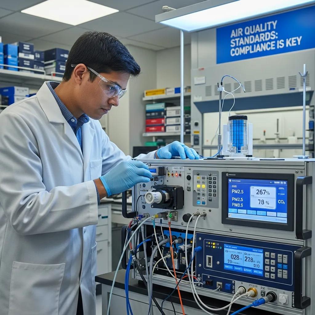
Why Is Breathing Air Quality Testing Essential for Compliance?
Breathing air quality testing verifies that compressed air meets the numeric limits defined by standards, supports the protection of users from acute and chronic exposure, and provides the documented evidence needed for audits and regulatory enforcement. Testing identifies failures in filtration, unexpected intake contamination, or compressor-related contamination such as oil carryover or elevated CO, allowing corrective actions before end users are harmed. Regular testing also reduces operational risk by detecting trends—rising CO or oil levels—that indicate maintenance needs, and it supports lifecycle planning for filter and adsorbent replacement. In addition to safety and legal reasons, proactive testing prevents costly downtime by ensuring compressors and purification systems perform reliably under load.
Supports human health: Verifies contaminant levels against defined thresholds.
Ensures regulatory compliance: Generates records required for audits and standards adherence.
Preserves equipment and gas quality: Identifies oil carryover or moisture that degrades fills.
Enables proactive maintenance: Reveals trends to plan filter and dryer replacement.
These testing motivations lead directly into the specifics of what contaminants are measured and how often tests should occur to maintain compliance.
contact LW Americas for project assistance when specifying system-level compliance.
What Contaminants Are Tested in Breathing Air Quality Services?
Breathing air testing typically measures carbon monoxide (CO), carbon dioxide (CO2), oil aerosol and vapor, particulates, water content or dew point, total hydrocarbons, and odor assessment where applicable. CO and CO2 are measured in ppm with portable analyzers or calibrated laboratory instruments because they represent acute toxicity and rebreathing risks; oil is measured as mg/m³ to assess compressor lubrication carryover; particulates are counted by size and density; and dew point sensors quantify moisture that can cause freeze-ups or microbial growth. Testing methods range from in-line continuous monitors for CO and dew point to periodic laboratory sampling for hydrocarbons and oil. Accurate measurement determines whether the breathing air meets the grade specified under CGA G-7.1 or the purity classes of ISO 8573-1.
This contaminant breakdown clarifies which instruments and sampling strategies are necessary to create defensible compliance records.
How Often Should Breathing Air Be Tested According to Standards?
Standards and best practices recommend baseline testing at installation and regular periodic testing thereafter. The frequency of these tests is not absolute but varies significantly based on several factors, including jurisdictional requirements, the specific application’s duty cycle, the manufacturer’s guidance for the equipment, and the risk profile of the environment. Common recommendations might suggest quarterly testing as a starting point, but increased frequency is often necessary under certain conditions such as changes to the intake environment, maintenance events, compressor work orders, or after repairs. Event-driven testing is essential when there is suspected contamination, unusual odors, filter bypass, or when intake conditions change (for example, nearby combustion sources). Recordkeeping should pair scheduled tests with event triggers and corrective actions, ensuring that trending data and remediation steps are documented. High-risk operations or those subject to stricter industry rules may require monthly or continuous monitoring for certain contaminants like CO or dew point, aligning with the most stringent applicable guidelines.
These scheduling principles help safety managers balance resource constraints with the need for timely detection and response to air-quality deviations.
What Are the Standards for High-Pressure Breathing Air Compressors?
High-pressure breathing air compressors influence air quality through design choices—lubrication type, duty cycle capability, sealing, and materials—that affect contaminant generation and the ease of purification. Standards expect compressors used for breathing air to allow integration of multi-stage filtration, CO mitigation technologies, and monitoring instrumentation while minimizing oil carryover and thermal spikes that generate CO. Design features such as continuous-duty capability, one-piece cast blocks, and lower RPM operation reduce mechanical wear and oil migration, which in turn supports sustained air purity. Proper compressor selection and system layout make it possible to meet CGA and ISO requirements reliably while maintaining throughput for cylinder fills or high-demand operations.
Compressor feature
Why it matters for air quality
Practical outcome / example
Continuous-duty operation
Maintains stable temperatures and load management
Lower CO generation and consistent dryer performance
One-piece cast blocks
Fewer joints reduce leakage and oil paths
Reduced oil carryover and improved durability
Lower RPM designs
Less wear and reduced vibration
Lower particulate and oil aerosol production
This table helps procurement and engineering teams prioritize features that materially reduce contaminant risks and maintenance burdens in breathing-air systems.
How Do Continuous-Duty Compressors Support Air Quality Compliance?
Continuous-duty compressors are engineered to run reliably under sustained load, which stabilizes operating temperatures and reduces thermal cycling that can increase CO formation and stress filtration systems. Thermal stability reduces temperature-driven oil vapor and hydrocarbon spikes, and continuous operation avoids the frequent cold starts that commonly elevate wear and oil migration. For high-throughput environments—industrial filling stations, dive shops, or fire departments—continuous-duty designs provide consistent flow and predictable integration with dryers and adsorption beds, simplifying compliance. Lower RPM operation inherent to many continuous-duty platforms also reduces vibration and mechanical wear, which helps limit particulate generation that would otherwise burden downstream filters.
These operational advantages explain why continuous-duty compressors are often specified in systems that must deliver reliable, standards-compliant breathing air under heavy or constant use.
What Features Ensure Compressors Meet CGA and ISO Standards?
Compressors and system components must include multi-stage filtration (pre-filters, coalescers, adsorbents), CO mitigation or monitoring, tight material and machining standards (e.g., one-piece cast blocks), and accessible maintenance points to reliably meet CGA and ISO requirements. Monitoring instrumentation—continuous CO sensors, oxygen monitors, and dew point sensors—provides real-time assurance and event logging, while filtration stacks sized for the expected flow rates ensure the specified ISO particle, water, and oil classes are achieved. Manufacturers that combine robust mechanical design with integrated purification and monitoring simplify compliance and reduce the risk of user error. Selecting systems with documented project support and design services makes implementation and validation more straightforward.
Operations should require specification documents that map each standard limit to a system component, maintenance activity, and monitoring strategy so compliance is auditable and operationally sustainable.
LW Americas’ continuous-duty compressor families, NitroxMakers, YachtPro systems, and breathing air purification and monitoring solutions illustrate how product-level choices—continuous-duty operation, durable cast components, lower RPM designs, and project support including 2D and 3D drawings—translate into systems engineered to meet CGA and ISO-driven specifications.
How Do NFPA 1989 and Industry-Specific Standards Impact Breathing Air Quality?
NFPA 1989 and other industry-specific standards add prescriptive requirements and operational mandates that can be stricter than general breathing-air standards, especially for emergency responders and medical applications. NFPA 1989 imposes expectations on SCBA filling stations, requiring documented testing, CO monitoring, and procedural controls to ensure cylinder fills are safe for firefighters during emergency response. Diving and medical sectors overlay their own preferences—diving often demands diving-grade specifications for Nitrox and Trimix fills, while medical uses may require the lowest achievable oil and particulate classes—so compliance strategies must integrate CGA and ISO limits with sector-specific rules. Understanding these layered expectations is essential for specifying purification, monitoring, testing cadence, and operational procedures that satisfy all applicable requirements.
Emergency services (NFPA): Increased emphasis on CO monitoring, recordkeeping, and procedural fills.
Diving operations: Tighter hydrocarbon and particulates control with documented mixing and blending procedures.
Medical systems: More stringent expectations for oil-free air and validated monitoring to protect vulnerable patients.
These industry overlays determine both technical specifications and operational controls needed to ensure compliant breathing-air supply.
What Are NFPA 1989 Requirements for Firefighting Breathing Air?
NFPA 1989 centers on respiratory protection for emergency responders and prescribes operational protocols for SCBA filling stations, including monitoring, testing frequency, and documentation to ensure cylinder fills meet safe limits. Key expectations emphasize CO limits, continuous or frequent monitoring for contamination, and procedural controls such as intake placement and source checks to prevent smoky or combustion-contaminated air from entering the system. Fire departments must maintain records of testing and corrective actions and ensure personnel training for safe filling operations. Practical compliance steps include installing permanent CO monitors, performing baseline and routine sample testing, and establishing clear maintenance schedules for filters and dryers.
Translating NFPA 1989 into daily practice reduces acute exposure risks for firefighters and ensures fills are safe during high-stress operational periods.
How Do Diving and Medical Industries Apply Breathing Air Standards?
Diving operations typically prioritize Grade E-like specifications and ISO classes that minimize hydrocarbons and CO to protect divers and gas mixtures; systems for dive shops often include Nitrox Makers and blending controls to achieve accurate oxygen concentrations and low contaminant levels. Medical breathing-air systems demand the tightest oil and particulate controls and may require higher testing frequency and validated documentation to meet patient-safety requirements. System design differences include choice of compression technology (oil-free vs. oil-lubricated with aggressive oil removal), redundant monitoring, and conservative replacement schedules for adsorbents. These sector-specific adaptations ensure the compressed air meets the intended physiological risk profile and regulatory expectations.
Industrial High-Pressure Air Compressor Systems: Applications and Solutions for Manufacturing and Energy Sectors
Please note: The content presented here is intended to provide conceptual frameworks and design principles related to high-pressure compressor systems. It is not intended as licensed engineering guidance, design specifications, or a substitute for professional engineering advice. Specific applications require detailed engineering analysis and adherence to all applicable codes and standards.
Industrial high-pressure air compressor systems compress and deliver gas at pressures significantly above standard plant pneumatic levels to power specialized machinery, perform pressure testing, and handle fuel compression tasks. These systems operate through multi-stage compression, intercooling, and precision valving to maintain stable delivery pressure and meet purity or safety requirements, which yields predictable process outcomes and reduced downtime. Understanding how continuous-duty designs, oil-free options, and application-specific accessories interact provides a framework for optimizing compressed air systems in manufacturing, CNG fueling, and energy-sector gas handling. This article explores core compressor types, component roles, manufacturing applications, and energy-sector uses, presenting conceptual frameworks for selection criteria, maintenance considerations, and energy-efficiency technologies. This discussion outlines conceptual implementation patterns for manufacturing compressed air systems, explores how CNG and biogas compression supports renewable fuels and vehicle fueling, and identifies accessory types—such as purification modules, boost pumps, and air amplifiers—that are integral for system integrity and throughput. The discussion integrates vendor capabilities sparingly to illustrate real-world solutions, focusing on conceptual technical considerations for professionals involved with industrial high-pressure compressor systems.
What Are Industrial High-Pressure Air Compressors and Their Key Benefits?
Industrial high-pressure air compressors are mechanical systems designed to raise the pressure of air or gas to levels typically required for specialty applications, often ranging from tens up to several hundred bar depending on the task. They achieve this through staged compression, intercooling, and robust mechanical design, providing stable, high-pressure delivery that enables reliable actuation, pressure testing, and filling operations across sectors. The main benefits include sustained uptime from continuous-duty capability, precise pressure control for process consistency, and enhanced safety and purity when paired with proper filtration and monitoring. In manufacturing and energy contexts, these attributes can contribute to reduced process variability, shorter cycle times, and support for regulatory compliance, particularly for specialized applications like breathing air or fuel-grade gas. The next subsection explains how continuous-duty compressors offer operational advantages and which engineering features make them suitable for nonstop industrial use.
How Do Continuous-Duty High-Pressure Compressors Enhance Industrial Operations?
Continuous-duty high-pressure compressors are engineered to run without frequent cool-down periods by using lower RPM components, robust cast blocks, and thermal management strategies that dissipate heat effectively during prolonged operation. This design reduces thermal stress on key components, maintains steady pressure delivery, and minimizes the risk of unplanned stops—improving overall equipment availability for critical manufacturing lines and fueling stations. Continuous operation also means fewer start/stop cycles, which decreases wear on valves and seals and lengthens maintenance intervals compared with intermittent-duty machines. For operations prioritizing uptime, continuous-duty designs offer a conceptual framework for predictable scheduling and smoother integration with storage tanks and downstream purification stages. Understanding these benefits highlights why customization is often a key consideration for aligning continuous-duty compressors with specific site constraints and purity requirements.
What Makes Custom High-Pressure Compressor Solutions Essential for Manufacturing and Energy?
Off-the-shelf compressors may not meet unique requirements for footprint, purity, pressure staging, or integration with existing plant controls, so custom solutions adapt core compressor designs to site-specific constraints and performance targets. A project-managed custom solution often involves stages such as requirements capture, compressor selection, engineering design, packaging, and site support, aiming to ensure the final system aligns with the operational and regulatory environment. Tailored systems can improve lifecycle cost and regulatory compliance by optimizing component selection and service access, which reduces downtime and simplifies maintenance planning. The decision checklist below presents considerations for determining when a custom approach might be preferred over a standard packaged unit.
Conceptual considerations for custom compressor solutions:
Space-constrained installations: When footprint or mounting orientation is non-standard.
Strict purity or breathing-air needs: When integrated inline purification and monitoring are critical design elements.
Process integration requirements: When controls, piping, or storage need bespoke interfaces.
Such a checklist can assist in prioritizing customization, and the following section compares major compressor families to inform initial selection considerations.
Which High-Pressure Compressor Types Are Best Suited for Manufacturing and Energy Applications?
Choosing the right compressor type depends on required pressure range, duty cycle, contamination sensitivity, and lifecycle costs; common families include reciprocating (piston), rotary screw, and specialized high-pressure piston assemblies for extreme pressures. Each family delivers different trade-offs in efficiency, maintenance cadence, footprint, and suitability for oil-free operation, making a structured comparison useful for selection decisions. Below is a compact comparison that maps compressor type attributes to typical use cases and operational considerations, providing a conceptual framework for professionals.
Different compressor types offer characteristic trade-offs useful during system selection.
Compressor Type
Typical Duty / Oil-Free Option
Typical Pressure Range
Best Use Cases
Reciprocating (piston)
Continuous to intermittent / Oil-free available
Up to 420 bar (for specialized systems)
High-pressure filling, pressure testing, CNG fill stations
Rotary screw
Continuous-duty / Often oil-lubricated, oil-free variants exist
Variable, often reaching up to 420 bar for specific models
Mobile filling, vessel service, remote fueling
It’s important to note that while some specialized reciprocating and compact units can reach pressures up to 420 bar, this represents the upper end of the spectrum for specific high-pressure applications, not a typical range for all industrial compressors. This comparison clarifies that reciprocating designs excel where very high pressures or compact high-pressure packages are required, while rotary screw units suit continuous plant air at moderate pressures. The next subsections explain advantages and trade-offs across these families and the role of oil-free design for contamination-sensitive industries.
What Are the Advantages of Reciprocating and Rotary Screw Compressors?
Reciprocating compressors deliver high discharge pressures in compact packages and are well-suited for intermittent high-pressure fills and testing operations because each piston stage produces substantial pressure increase per stroke. They typically have higher peak efficiency at high pressures but may require more frequent valve and seal maintenance compared with rotary screw machines, which trade slightly lower peak efficiency for smoother operation and fewer vibration-related issues. Rotary screw compressors offer continuous-duty reliability with simpler vibration profiles and often integrate well with variable speed drives for energy savings on variable flow applications. Design principles often suggest reciprocating machines for extreme pressure or compact mobile systems, while rotary screws are typically considered for steady, high-volume plant compressed air where lower maintenance frequency and reduced vibration are priorities. These trade-offs point to oil-free considerations discussed next, particularly for breathing air and medical uses.
How Do Oil-Free and Continuous-Duty Compressors Improve Efficiency and Safety?
Oil-free compressors are designed to mitigate oil carryover risk into the compressed air stream, supporting compliance with purity standards, particularly those referenced in industry guidance for applications like breathing air and sensitive manufacturing processes. The mechanism is simple: oil-free designs use materials and clearances that avoid oil lubrication in the compression chamber or rely on separation stages that prevent contamination, protecting downstream processes and product quality. Continuous-duty capability complements oil-free design by maintaining stable temperatures and pressures that can reduce condensation and microbial growth risks in compressed-air networks. For regulated applications such as medical gas, food processing, and breathing air, the combination of oil-free compression with effective purification and monitoring is a critical design consideration for ensuring safety and compliance. Having considered compressor families and purity choices, the following section explores concrete manufacturing applications and system design patterns.
How Are High-Pressure Systems Applied in Manufacturing Compressed Air Solutions?
High-pressure air systems in manufacturing power specialized equipment, enable high-precision testing, and provide process air for material handling, cutting, and automated tooling; the design must balance pressure, flow, storage, and purity. Typical system architectures include a high-pressure compressor, intercooler and aftercooler stages, purification modules, storage receivers, and controlled distribution piping with safety valves and monitoring. Conceptual design for manufacturing often involves addressing transient loads—such as rapid pressure swings during press or test rig cycles—and may incorporate storage and boost pumps to buffer demand and sustain pressure during peaks. Below is a focused list of primary manufacturing applications and approximate pressure ranges, intended to assist in conceptually matching compressor selection to use-case requirements.
Primary manufacturing applications and their pressure profiles include the following.
Manufacturing uses of high-pressure air:
Pneumatic presses and actuators: Typically require 6–40 bar for high-force applications, and sometimes higher for specialized presses.
Pressure testing and leak detection: Often use 100 bar, with specialized applications reaching up to 420 bar depending on vessel rating and test standard.
Cleaning and material handling (blow-off, pneumatic conveyors): Use 6–10 bar for general tasks and higher pressures for dense material transport.
These applications illustrate the importance of integrated design—conceptually matching compressor capacity, storage, and downstream purification—and the next subsection highlights how custom packaged solutions can address these manufacturing challenges.
What Are the Primary Manufacturing Uses of High-Pressure Air Compressors?
Manufacturing environments rely on high-pressure air for actuation of heavy tooling, precision pressure testing of welded assemblies, and high-velocity cleaning or cutting processes that require consistent pressure and pulsation control. Pressure testing of fittings, cylinders, and safety devices may demand pressures approaching the compressor’s upper rating, a scenario that conceptually requires robust staging and safety systems to mitigate overpressure risks. Material handling and pneumatic conveyance benefit from booster stages or air amplifiers to increase flow at point-of-use without overtaxing the main compressor, enhancing throughput while limiting upstream cycling. These practical uses underscore the importance of appropriate sizing, storage, and accessory selection for maintaining efficiency and safety, leading into a short vendor-focused callout illustrating how tailored solutions can contribute.
How Do LW Americas’ Custom Solutions Address Manufacturing Challenges?
LW Americas offers continuous-duty high-pressure compressor systems and tailored project management, aiming to align compressor selection with manufacturing needs while emphasizing system durability through design choices such as one-piece cast blocks and lower RPM operation. Their approach encompasses coordination of compressor selection, and providing 2D/3D design drawings and packaging options that can simplify mechanical integration in various operational environments. By combining engineered packaging with responsive North American support and accessories—such as purification modules, filling devices, and boost pumps—these solutions are designed to reduce installation time and help ensure the delivered package addresses purity and footprint requirements. This vendor-level capability illustrates how a managed custom workflow can shorten specification cycles and reduce integration risk, transitioning naturally to energy-sector compression roles discussed next.
What Roles Do CNG Compressor Systems Play in Energy Sector High-Pressure Gas Applications?
CNG and biogas compressor systems enable conversion of low-pressure gas into high-pressure forms suitable for vehicle fueling, pipeline injection, and storage, supporting both conventional natural gas and renewable natural gas (RNG) value chains. These systems typically use multi-stage reciprocating compression with intermediate cooling and cleanup stages to handle variable gas quality and ensure the compressed fuel meets fueling or grid injection specifications. It is crucial to note that while the principles of compression are similar, systems handling natural gas or biogas require specific material selection, safety features, and design modifications compared to those used for air, due to the distinct chemical properties and potential hazards of these fuel gases. Key system design considerations include gas purification upstream of compression, materials compatibility for biogas constituents, and efficient thermal management for controlling discharge temperatures and lubricants. The next subsection describes how CNG and biogas compressors integrate into fueling infrastructure and renewable gas handling workflows.
How Do CNG and Biogas Compressors Support Renewable Energy and Vehicle Fueling?
Compressors specifically designed for CNG and biogas convert produced or farmed biogas and RNG into pressurized fuel for CNG vehicles or pipeline injection, often in staged compression steps to reach 200–250 bar for vehicle cylinders or pipeline pressure specifications. Unlike air compressors, these systems require specialized components and safety protocols to handle flammable and corrosive gas mixtures. Integration with gas cleanup and moisture removal is a critical design consideration to mitigate corrosion, hydrate formation, and particulate fouling that can compromise seals and valves; when treating biogas, material selection and filtration approaches often need to address siloxanes and other contaminants. Operational considerations include intermittent versus continuous fueling demand, storage sizing, and site-level heat recovery to improve overall plant efficiency. Properly designed CNG compressor systems conceptually link renewable gas sources to end-use markets, and the next vendor-focused subsection highlights product attributes that can support energy efficiency.
What Are the Benefits of LW Americas’ High-Pressure Compressors for Energy Efficiency?
LW Americas’ continuous-duty, lower-RPM compressor designs and one-piece cast block construction contribute to durability and reduce mechanical losses that can translate into energy and lifecycle advantages for CNG and biogas applications. When paired with integrated project management and responsive support, these design attributes aim to ensure the compressor is sized and staged appropriately, which can mitigate throttling and part-load inefficiencies often associated with poorly matched systems. The company’s product range—covering mobile, compact, stationary, and silent units, with specialized models reaching up to 420 bar—provides options for fueling stations, mobile fueling units, and pipeline boosting where energy performance and uptime are priorities. These vendor capabilities illustrate how CNG and biogas equipment selection and system-level design conceptually interact to impact efficiency, moving the discussion next to components and accessories that can optimize performance.
Which Components and Accessories Optimize High-Pressure Compressor System Performance?
A high-pressure compressor package is only as effective as its supporting components: purification systems, breathing air monitoring, filling devices, boost pumps, storage tanks, valves, and safety accessories all shape safety, purity, and throughput. Purification stages are designed to remove oil, particulates, moisture, and hydrocarbons to meet application-specific purity targets. Separately, breathing air monitors provide continuous verification for safety-critical air supplies, a distinct and highly regulated application. Boost pumps and filling devices manage flow and pressure at point-of-use, reducing main compressor cycling and improving fill rates, and air amplifiers can increase localized pressure for short-duration tasks without oversized main compressors. The table below clarifies component functions, typical benefits, and common specifications, offering a conceptual framework for system designers to consider which accessories to incorporate.
Key components and their roles in system performance.
Component
Primary Function
Typical Benefit / Spec
Purification system
Remove contaminants (oil, moisture, particulates)
Supports ISO-level air quality; protects downstream equipment
Breathing air monitor
Real-time air quality verification
Safety assurance for breathing air; alarm and interlock capability
Filling device / booster pump
Increase local pressure and flow
Faster fills; reduced main compressor cycling
Air amplifier
Localized pressure boost without large compressor
Cost-effective short-duration pressure increase
How Do Purification Systems and Breathing Air Monitoring Enhance Safety and Quality?
Purification systems typically combine coalescing filters, dryers, activated carbon, and adsorbents to remove oil vapor, moisture, and hydrocarbons to meet application-specific purity targets, and their selection depends on inlet air quality and required ISO 8573-1 classes. Breathing air monitoring complements purification by tracking oxygen levels, CO, hydrocarbons, and particulate concentrations, triggering alarms and interlocks when readings exceed safe thresholds. The conceptual placement of monitors is often considered critical—typically after final filtration but before distribution—to help ensure that any degradation in purification performance is detected prior to user exposure. For regulated breathing-air duties and sensitive manufacturing, combining multi-stage purification with continuous monitoring is a key design principle for supporting compliance and operator safety, which naturally brings attention to boost pumps and filling devices that can enhance operational flexibility.
What Are the Functions of Filling Devices, Boost Pumps, and Air Amplifiers?
Filling devices and boost pumps raise pressure locally to speed vessel fills or maintain pressure during peak demand, reducing the need to oversize the main compressor and smoothing transient loads on the plant system. Air amplifiers use the Venturi effect or staged boosting to increase localized pressure for short-duration tasks, offering a cost-effective alternative where continuous high pressure is unnecessary. Conceptual integration often involves check valves, pressure relief mechanisms, and monitoring to mitigate backflow or overpressure conditions. Maintenance frameworks typically recommend routine inspection of seal integrity and flow paths. The selection of these accessories, based on duty cycle and fill-rate requirements, can contribute to improved throughput and reduced wear on core compression equipment. The next section covers energy-efficiency measures and maintenance practices that extend equipment life.
How Can Energy Efficiency and Maintenance Practices Extend the Life of High-Pressure Compressors?
Proactive energy-efficiency measures and structured maintenance programs reduce operating costs and extend compressor life by minimizing stress, optimizing control, and catching wear patterns early through monitoring. Technologies like variable speed drives (VSDs), heat recovery systems, and IoT-enabled condition monitoring deliver quantifiable savings and predictive maintenance insights while introducing implementation considerations such as control complexity and payback timelines. Routine maintenance—filter changes, vibration analysis, oil and seal inspections, and scheduled overhauls—prevents performance degradation and avoids catastrophic failures that lead to long downtimes. The table below compares efficiency technologies by expected energy impact, maintenance benefits, and implementation considerations, offering a conceptual framework for decision-makers to balance ROI and operational readiness.
Efficiency technologies compared for decision-making.
Technology
Energy Impact
Maintenance / Implementation Consideration
Variable Speed Drive (VSD)
Potential for substantial savings in variable-load scenarios
Adds control complexity; requires soft-start and harmonics management
Heat recovery
Captures waste heat for plant use
Reduces net energy consumption; needs space and integration
IoT condition monitoring
Lowers unplanned downtime via alerts
Requires sensors and analytics; improves spare-part planning
What Are Best Practices for Maintaining Continuous-Duty High-Pressure Compressors?
A robust maintenance framework for continuous-duty compressors often encompasses monthly visual and operational checks, quarterly filter and oil-level verification (if applicable), and annual vibration and thermal analysis to identify early signs of wear. Predictive maintenance focuses on monitoring temperature, vibration spectra, and oil condition (when present) to schedule interventions before failures occur; maintaining a critical-spares list for valves and seals shortens repair times. Documentation of running hours and load patterns can inform overhaul timing and support the conceptual justification for investments in upgrades like VSDs or enhanced cooling. Implementing these practices can contribute to reduced unplanned downtime and extended component life, which supports broader energy-efficiency considerations discussed next.
How Do Energy-Efficient Technologies Reduce Operational Costs in Industrial Settings?
Energy-efficient technologies such as VSDs, heat recovery, and IoT monitoring deliver measurable operational savings by matching compression output to demand, reusing waste heat for plant processes, and enabling early fault detection to avoid inefficient operation. VSDs reduce energy consumption during partial-load operation by adjusting motor speed to demand, offering significant savings depending on duty profile, while heat recovery can offset process heating loads and shorten payback on larger installations. IoT monitoring reduces lifecycle costs by optimizing maintenance scheduling and reducing catastrophic failures, though it requires upfront sensor and analytics investment. Balancing these options against implementation complexity and expected ROI provides a conceptual framework for achieving sustained cost reductions and reliability. For teams seeking vendor support for design, drawings, and delivery, LW Americas offers project-managed compressor solutions, including custom 2D/3D drawings and support for system integration.
Operational savings: VSDs and heat recovery lower net energy costs through demand matching and reuse of thermal energy.
Maintenance savings: IoT monitoring reduces downtime and extends component life by enabling predictive repairs.
Implementation trade-offs: Upfront costs and control complexity must be weighed against lifecycle savings and reliability goals.
Explore Tailored High-Pressure Solutions
For specific quotes, custom designs, 2D/3D drawings, and project-managed compressor selection, connect with LW Americas for tailored high-pressure solutions and responsive North American support.
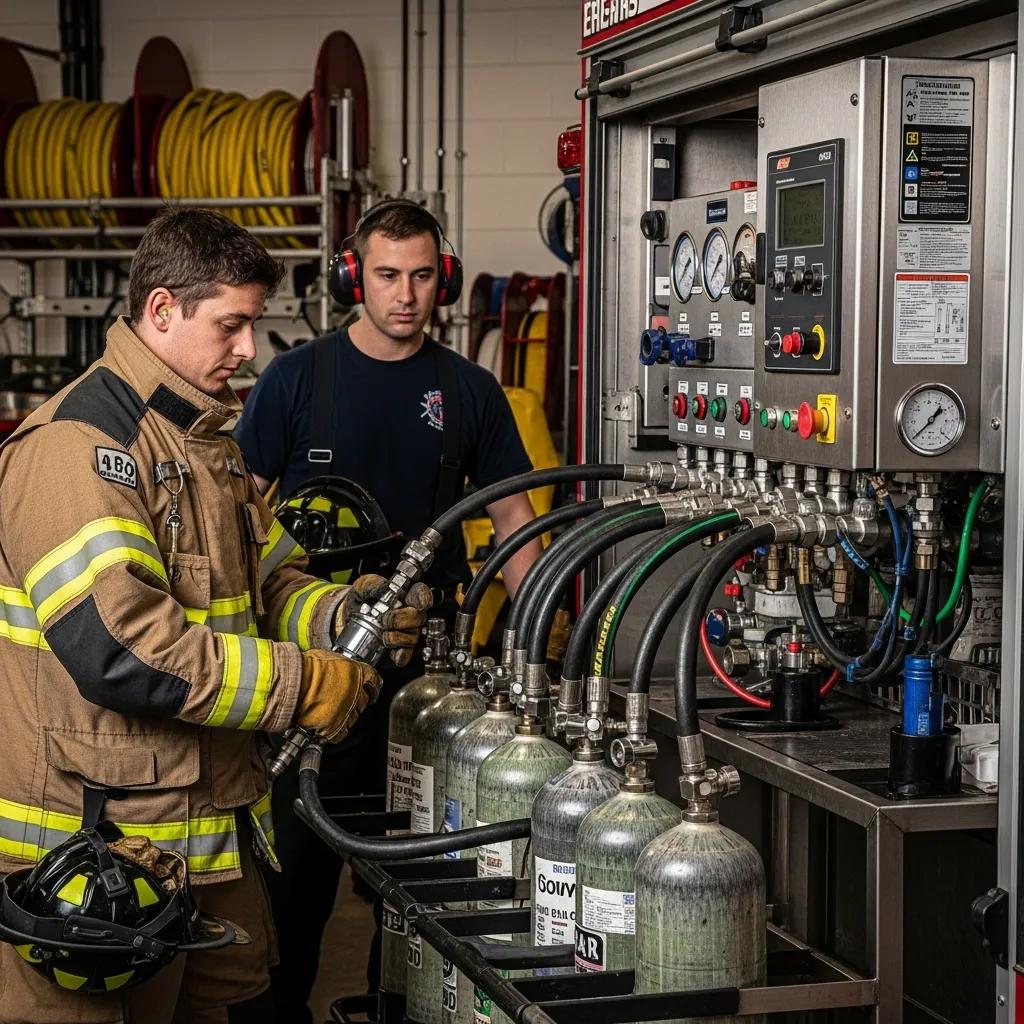
SCBA Fill Station Setup: Complete Guide for Fire Departments to Design, Operate, and Maintain Safe Breathing Air Systems
An SCBA fill station is the centralized system a fire department uses to compress, purify, store, and dispense breathing air for self-contained breathing apparatus (SCBA), supporting daily training and emergency responses. This guide explains how to design, size, and operate an SCBA fill station so crews maintain readiness, minimize downtime, and are designed to align with air-quality requirements, often referencing standards such as NFPA 1989, which is commonly adopted by many fire departments. Specific requirements can vary by Authority Having Jurisdiction (AHJ) and local regulations. Readers will learn needs assessment methods, equipment selection criteria, purification and monitoring approaches, storage and fill-panel layout considerations, plus operation, maintenance, and troubleshooting best practices. The article also highlights practical vendor-grade options and project support examples to show how manufacturers can simplify design and installation without dictating choices. Start here with an operational definition and proceed through design checklists, compressor comparisons, purification EAV tables, and a maintenance matrix that together form a complete blueprint for breathing air system setup and sustained alignment with standards.
What Is an SCBA Fill Station and Why Is It Critical for Fire Departments?
An SCBA fill station is a breathing air system designed to compress ambient air to high pressure, filter contaminants, store the compressed air, and supports safe filling of SCBA cylinders for firefighter use. It works by combining a high-pressure air compressor with multi-stage purification, high-pressure storage (cascade) tanks, and a distribution/fill panel to aim to provide cylinders with air that aligns with health and safety criteria. The primary benefit is reliable on-site access to breathing air that is designed to align with recognized standards, which can help reduce response delays and address operational risks associated with using off-site fills. Understanding this central role sets the stage for how design choices can influence safety, readiness, and alignment with commonly adopted regulatory guidelines, such as those found in NFPA 1989. It’s important to note that specific requirements vary by Authority Having Jurisdiction (AHJ) and local regulations.
How Does an SCBA Fill Station Support Firefighter Safety and Operations?
An on-site SCBA fill station supports rapid cylinder turnaround by enabling immediate refills after training or incident use, which can contribute to improved crew readiness and help reduce response gaps. The mechanism begins with continuous-duty compressors that deliver required flow to the purification train and cascade storage so multiple cylinders can be filled in sequence, limiting queuing during peak demand. Operationally, integrated air quality monitoring helps detect potential contaminated fills by flagging CO, CO2, or oil vapor excursions and triggering isolation or shutdown actions. Having these capabilities on site translates into measurable improvements in fill-rate performance and reduces logistical dependence on external suppliers, which benefits both daily operations and emergency surge scenarios.
What Are the Different Types of SCBA Fill Stations Used by Fire Departments?
Fire departments typically deploy several fill station configurations—stationary centralized systems for main stations, mobile trailer-mounted units for on-scene or regional mutual aid, cascade-only storage for high-volume buffering, and hybrid combinations that mix fixed compressors with mobile support. Stationary systems are optimized for consistent high-throughput filling at a fixed location, while mobile systems serve as crucial situational support tools, prioritizing transportability, ruggedness, and on-scene refilling capability for remote training, emergency deployment, or temporary field support. Cascade storage systems act as high-pressure reservoirs that enable simultaneous rapid fills without immediate compressor output matching every demand spike. Selecting among these types depends on mission profile, geographic coverage needs, and expected fill cycles, which leads directly into design and selection criteria.
How to Design an Effective SCBA Fill Station for Fire Department Needs?
Designing an effective SCBA fill station starts with a systematic needs assessment followed by equipment selection, layout planning, and validation testing to support performance and safety goals. First quantify duty cycle, peak simultaneous fills, and future growth to size compressor capacity and cascade storage; then plan ventilation, noise control, and safety interlocks for the installation area. Incorporate purification and monitoring specifications that are designed to align with air-quality criteria, often referencing standards like NFPA 1989, which is commonly adopted by many fire departments. Specific requirements can vary by Authority Having Jurisdiction (AHJ) and local regulations. Document the system design in drawings and bills of material for procurement and commissioning. Good design can help reduce installation risk and simplify maintenance, so a clear project plan with deliverables and acceptance testing is essential before purchasing equipment.
The core steps for SCBA fill station design are:
Assess demand and duty cycle to determine required compressor flow and cascade capacity.
Select compressor technology and purification train matching air-quality and redundancy needs.
Design storage, fill panel layout, ventilation, and safety interlocks for the installation footprint.
Specify monitoring, testing protocols, and record-keeping designed to align with recognized standards, such as NFPA 1989, and other applicable local regulations.
Plan commissioning tests and ongoing maintenance schedules to validate performance.
These steps form a practical roadmap for design decisions and then guide specific component selection for compressors, purification, and storage.
What Are the Key Components in SCBA Fill Station Design?
Key components include the high-pressure compressor (multi-stage or reciprocating), a purification train (coalescing filters, molecular sieves, catalytic CO removal where required), high-pressure cascade storage tanks, a calibrated fill panel or manifold with gauges and pressure relief devices, and continuous air quality monitors for CO/CO2 and oil vapor. The compressor is the workhorse that determines flow-rate and pressure capabilities, while the purification train aims to support purity testing protocols for the compressed air to align with specified contaminant limits. Fill panels provide controlled distribution to cylinders and support safe filling procedures, and monitoring devices provide both real-time alarms and data logs for audits—each piece is interdependent in supporting the delivery of breathing air that is designed to align with standards.
Component
Function
Typical Specification
High-pressure compressor
Generates compressed air to required PSI and flow
Rated for pressures typically ranging from 4500–5000 psi service with continuous-duty capability
Purification train
Filters and captures particulates, oil, CO, VOCs
Multi-stage filters with molecular sieves and CO/CO2 monitoring
Cascade storage
Stores high-pressure air for rapid fills
Multiple high-pressure tanks for staged filling and redundancy
Fill panel / manifold
Distributes air to SCBA cylinders
Includes gauges, relief valves, and controlled outlets
Monitoring devices
Continuous air-quality alerts and logging
CO/CO2 sensors with alarm thresholds and data recording
This component matrix clarifies how each element contributes to system performance and informs procurement specifications for reliable operation.
How Do NFPA 1989 and Other Standards Influence SCBA Fill Station Design?
NFPA 1989 is a widely referenced standard that defines breathing air quality criteria, provides frameworks for testing intervals, and sets acceptable contaminant limits. It directly shapes purification train selection, monitoring thresholds, and validation testing for many SCBA fill stations. Complementary references like NFPA 1500 and CGA guidance also influence installation practices, operator training, and periodic hydrostatic testing of cylinders and tanks. While NFPA 1989 is commonly adopted by many fire departments, specific requirements can vary by Authority Having Jurisdiction (AHJ) and local regulations. These standards often require documented testing and records that demonstrate ongoing alignment with their guidelines, so design choices should prioritize test points, sample ports, and accessible monitoring for routine verification, with specific testing intervals typically ranging based on usage and jurisdiction. Incorporating acceptance tests into commissioning, aligned with adopted standards, supports the validation of the installed system against documented requirements and its readiness for operational use.
Which High-Pressure Air Compressors Are Best for Fire Department SCBA Fill Stations?
The best compressors for SCBA fill stations are continuous-duty, high-pressure units designed for sustained operation with robust cooling and service access, often optimized for lower operating speeds. Continuous-duty designs reduce thermal stress and allow longer run times during large filling campaigns, while architectures optimized for lower operating speeds reduce wear and vibration, which can contribute to extended service intervals. Stationary compressors are the primary solution, offering higher sustained flow and are ideally suited to centralized fill rooms for consistent, high-volume refilling. Mobile compressors, while portable, are best utilized as situational support tools for remote training, emergency deployment, or temporary field support, rather than as replacements for fixed installations. They often have constraints in power availability, cooling capacity, and maintenance access compared to their stationary counterparts. Choosing between types requires matching rated flow (CFM), discharge pressure (PSI), footprint constraints, and maintenance capacity to the department’s fill-rate and operational profile.
Compressor Type
Continuous Duty
Rated Pressure
Typical Flow (CFM)
Typical Use Case
Stationary compressor
Yes
4500–5000 psi
High (sustained)
Central station high-volume refilling
Mobile compressor
Some models
Pressures up to 5000 psi
Moderate
Situational support for on-scene refilling, remote training, or temporary field deployment
Tankfill (small-scale)
Varies
3000–4500 psi
Low–moderate
Small houses or training fills
What Are the Benefits of Continuous-Duty, Low RPM Compressors for Fire Departments?
Continuous-duty compressors, often designed for lower operating speeds, offer engineering advantages such as reduced mechanical stress, lower operating temperatures, and diminished vibration, which together can contribute to increased reliability and potentially extended service intervals. Practically, these benefits can contribute to fewer unscheduled outages, predictable maintenance windows, and potentially reduced lifecycle cost due to lower component wear. For fire departments that rely on uninterrupted access to breathing air, the smoother operation and potentially extended periods between service events support operational readiness and can help reduce the risk of compressor-related fill interruptions. These reliability improvements dovetail with purification and monitoring investments to support the delivery of consistent breathing air that is designed to align with standards.
How to Choose Between Mobile and Stationary SCBA Compressors?
Deciding between mobile and stationary compressors hinges on mission profile, expected fill volume, geographic coverage, and budget constraints. Stationary units are the foundational choice, excelling for centralized high-throughput needs and continuous operation. Mobile units, conversely, are optimal for incident support, remote refilling during training, or temporary field support where a fixed installation is not feasible or available. It is important to recognize that mobile units typically have limitations regarding sustained power availability, cooling capacity, and ease of maintenance access compared to dedicated stationary systems. Consider scenarios such as multi-station mutual aid, remote training events, or rural coverage to determine whether portability for situational support or consistent high-volume capacity is the priority. Evaluate footprint, electrical and ventilation requirements for stationary installs versus towing, mounting, and environmental protection for mobiles. The decision should align compressor capability with the department’s operational tempo and long-term plans, and include contingency planning for redundancy or temporary mobile augmentation without suggesting portable units replace the primary role of fixed installations.
How to Ensure Breathing Air Purification Meets Fire Department Standards?
Supporting breathing air purification to align with standards typically involves a multi-stage filtration approach, continuous and periodic monitoring, and a documented testing program tied to acceptance criteria from adopted standards. Purification typically involves multi-stage filtration that captures particles and oils, along with activated carbon or catalytic elements for hydrocarbons and VOCs, and molecular sieves for moisture control, combined with CO/CO2 sensors that can provide alarms before cylinder filling. Implement sampling points and test procedures into the system design so technicians can periodically verify contaminant levels under load. Establishing clear alarms, isolation protocols, and corrective actions in SOPs aims to ensure that any deviation from acceptable air quality is detected and addressed before providing air to firefighters.
What Filtration and Monitoring Systems Are Essential for SCBA Breathing Air?
Essential filtration and monitoring components include a staged filter train (pre-filter, coalescing oil remover, activated carbon or catalyst for hydrocarbons, and molecular sieve for moisture), plus continuous CO and CO2 monitors and oil vapor detectors. These elements work together to capture particulates, hydrocarbon vapors, and moisture that could potentially compromise cylinder air quality, while monitors provide immediate alerts and logging to support compliance. Proper sizing of filter elements and scheduled replacement intervals are critical, and alarms should be integrated into fill-panel controls so filling can be halted automatically when sensors exceed thresholds. This combination of filtration and monitoring is the backbone of breathing air systems designed to align with standards.
Purification Component
Removes
Monitoring / Threshold
Particulate / coalescing filter
Particles, liquid oil
Visual pressure differential; replace per hours
Activated carbon / catalyst
Hydrocarbons, VOCs
Periodic sampling; alarm on breakthrough
Molecular sieve / dryer
Moisture
Relative humidity indicators; dew point specs
CO / CO2 sensors
Combustion gases
Alarms at commonly referenced ppm thresholds (e.g., those found in NFPA 1989), supporting compliance with adopted standards.
These components must be matched to the compressor’s oil type and operating profile to support effective contaminant management through detection and filtration, and reliable monitoring.
How Does Compliance with NFPA 1989 Affect Breathing Air Purification?
NFPA 1989 is a widely referenced standard that sets measurable air-quality limits and provides frameworks for testing intervals. These often directly inform filter selection, monitoring alarm setpoints, and sample testing frequency for many fire departments. Systems are typically validated at commissioning and routinely re-tested to demonstrate ongoing alignment with adopted standards, with re-testing intervals typically ranging based on usage and jurisdiction. While NFPA 1989 is commonly adopted, specific requirements can vary by Authority Having Jurisdiction (AHJ) and local regulations. Adherence to adopted standards influences acceptance criteria such as acceptable ppm levels for CO and hydrocarbon presence, dew point limits, and documentation of corrective actions when limits are exceeded, with specific testing frequencies often outlined by the Authority Having Jurisdiction (AHJ) and manufacturer guidance. A compliance-driven approach requires integrating test ports, accessible sampling points, and a log system to record monitoring data, filter changes, and corrective maintenance, supporting auditors in tracing the system’s performance history and corrective measures if needed.
What Are Best Practices for SCBA Fill Station Operation, Maintenance, and Troubleshooting?
Best practices include establishing clear SOPs for operation and emergency shutdown, scheduling preventive maintenance aligned with duty cycles (with specific schedules typically ranging based on manufacturer guidance and local requirements), maintaining meticulous records for filters, oil changes, hours, and test results, and training personnel on first-line troubleshooting steps. A preventive maintenance matrix helps ensure critical tasks occur at appropriate intervals, which can vary based on duty cycle and manufacturer recommendations, and that parts such as filters and seals are replaced before failure. Troubleshooting protocols should start with basic diagnostics—power and controls checks, filter differential pressure, and sensor calibration—escalating to manufacturer support for specialized compressor block or purification failures. Implementing these practices reduces downtime and supports readiness for audits against adopted standards.
Everyday operational checklists and preventive maintenance routines keep a fill station reliable and aligned with standards while enabling rapid diagnosis when faults arise. While specific routines can vary, common frameworks include:
Daily checks: Visual inspection, oil level, drain moisture traps (these are common daily tasks).
Weekly checks: Monitoring differential pressure across filters and verifying alarms and gauges are common weekly tasks.
Monthly/quarterly: Replacing filters per manufacturer hours, calibrating sensors, and recording compressor hours are common monthly/quarterly tasks, though specific schedules should align with manufacturer guidance and local requirements.
These routine activities ensure system reliability and provide documentation for compliance audits, leading into a structured maintenance schedule and record-keeping approach.
How to Develop a Maintenance Schedule and Record-Keeping for SCBA Compressors?
Develop a maintenance schedule by mapping tasks to frequencies based on duty cycle and manufacturer guidance. This often includes daily checks, weekly operational verifications, and quarterly filter/service intervals, with annual major inspections including oil analysis and valve servicing. However, specific frequencies should always align with manufacturer recommendations and local requirements. Records should capture task, date, technician, compressor hours, filter part numbers, test results, and any corrective actions to create a history that supports audits. Digital logs with timestamped entries simplify trend analysis and support predictive maintenance, while paper backups can help meet basic record-retention requirements. Consistent record-keeping reduces risk and can demonstrate due diligence during inspections.
Task
Frequency
Record Type
Visual system inspection
Daily
Daily log entry
Oil level and leak check
Weekly
Service checklist
Filter element replacement
Per manufacturer hours / typically quarterly (actual frequency varies by usage and manufacturer guidance)
Parts log with serials
Sensor calibration and sample testing
Typically monthly/quarterly (actual frequency varies by usage and jurisdiction)
Test reports with ppm values, supporting compliance with adopted standards
Annual compressor overhaul
Typically yearly (actual frequency varies by usage and manufacturer guidance)
Service report and parts list
A structured matrix like this aligns maintenance actions with documented outcomes and supports compliant record retention.What Are Common Troubleshooting Steps for SCBA Fill Station Issues?
When facing common issues such as compressor failure to start, low fill rate, or contamination alarms, follow a tiered troubleshooting flow starting with operator-level checks, moving to technical diagnostics, and escalating to manufacturer support as needed. Begin by verifying power, control settings, and safety interlocks; if a low flow condition persists, check filter differential and suction conditions, and inspect for leaks in the cascade or fill panel. For contamination alarms, isolate the compressor, suspend fills, record sensor readings, and perform sample testing to confirm alarm validity before corrective remediation. Escalate to qualified service for compressor block, pump failures, or persistent contamination that simple filter changes do not resolve.
Basic diagnostics: Verify power and control status; reset alarms if needed.
Escalation: Contact qualified technical support for compressor block or purification train failures.
Following a clear escalation path can help preserve safety and minimize downtime while ensuring issues are addressed at the correct technical level.
Why Choose LW Americas for Custom SCBA Fill Station Solutions and Support?
LW Americas offers continuous-duty high-pressure compressors and gas systems designed to support life-safety applications, including offerings across tankfill compressors, stationary compressors, mobile compressors, filling panels, storage solutions, purification systems, and breathing air monitoring devices. Their product portfolio emphasizes continuous-duty operation, robust one-piece cast block construction, and designs optimized for lower operating speeds that reduce wear—attributes that can contribute to long-term reliability and potentially lower maintenance needs for fire department use. LW Americas also positions itself to provide responsive North American support and project management services that span equipment selection through design and installation oversight, making them a practical partner for departments seeking a turnkey design-to-support pathway that aims to align with commonly adopted standards, such as NFPA 1989, while acknowledging that specific requirements vary by Authority Having Jurisdiction (AHJ) and local regulations.
How Does LW Americas Provide Project Management and 2D/3D Design for Fire Departments?
LW Americas supports fire departments through a structured project workflow that begins with needs assessment and moves through equipment selection, 2D/3D system design, installation oversight, commissioning, and post-installation support. Deliverables typically include design drawings, bills of material, and commissioning reports that document performance against specified acceptance tests, which helps reduce installation risk and aims to ensure components are laid out for maintainability and alignment with adopted standards. Final compliance validation should always be coordinated with the Authority Having Jurisdiction (AHJ). Their project management approach aims to coordinate site requirements, ventilation, and safety interlocks with equipment delivery and commissioning to provide a coherent handover that includes operating and maintenance guidance for local staff.
What Are the Unique Value Propositions of LW Americas’ SCBA Fill Station Products?
Continuous-duty compressors: Support long run times and surge demands.
Designs optimized for lower operating speeds: Can contribute to reduced wear and maintenance frequency.
Project management & design: Can help minimize installation risk and supports documentation for compliance.
These product and service strengths can help a department translate technical requirements into a working, maintainable SCBA fill station configured to support their operational needs. Their local support presence in North America supports faster response for parts and technical queries, while custom solution capabilities and comprehensive project management reduce installation complexity. These attributes collectively support reliable fill-station uptime, predictable maintenance costs, and can facilitate compliance verification during audits against adopted standards, which are practical outcomes for departments managing life-safety infrastructure.
Stationary high pressure compressors for the compression of hydrogen, natural gas and biogas. Our compressors are characterized by a sturdy construction, low speed, long service intervals and an excellent value for money.
LW 1300 EG
LW1300 EG with water cooling
Take profit of our know-how in planning and construction of special systems, e.g. natural gas stations, biogas compressors for industrial large-scale plants, hydrogen systems and energy storage.
Applications
Type
From
To
Inlet pressure
atmospheric
150 bar (2100 psi)
Delivery capacity
6 m3/h (3,5 cfm)
700 m3/h (420 cfm)
Final pressure
10 bar (140 psi)
420 bar (6100 psi)
We individually calculate compressor and drive power according to your application requirement. In this way, we perform the best possible efficiency and highest economic feasibility for you.
Standard equipment
Sturdy, warp resistant steel frame with high quality industrial coating
Final pressure gauge, electric control system according to requirements and application
Automatic stop at final pressure
Automatic condensate drain
All pistons c/w steel piston rings at all stages
Hardened compression cylinders
Oil lubrication
Oil- / Water separators after each stage
Safety valves after each stage
Final pressure safety valve
Pressure maintaining and non return valve, HP outlet
Explosion proofed external components for EX zone 1
Options
Primary pressure calibration to adjust the desired inlet pressure
Inlet buffer tank 150 l, incl. safety valve, manual condensate drain valve, pressure gauge and electrical cut-off solenoid for inlet gas
Primary pressure monitoring – pressure shut off at max./min. inlet pressure
Electronic Compressor Control – ECC
Auto start for semi / full automatic mode
Inter-stage pressure gauge
Oil pressure gauge and monitoring c/w auto shut down
Puracon filter monitoring
Compressor block heating for ambient temperature < +5°C
Water cooling with stainless steel heat exchanger
Additional oil lubrication circuit allows oil changes during operation
Filter extension (larger or second filter housing)
We deliver high-pressure compressors and the complementary modules for purification, storage and filling.
High performance complete solutions for reliable compression, purification, storage and recovery of inert gases such as helium and argon. This compressor series provides economic efficiency to the maximum due to loss-free compression by means of returning condensation and leak gases.
Take profit of our many years of experience in planning and construction of special systems for applications such as helium recovery, filling plants and different test plants as well as various other helium applications.
Applications
Type
From
To
Inlet pressure
atmospheric
150 bar (2100 psi)
Delivery capacity
6 m3/h (3,5 cfm)
700 m3/h (420 cfm)
Final pressure
10 bar (140 psi)
420 bar (6100 psi)
We individually calculate compressor and drive power according to your application requirement. In this way, we perform the best possible efficiency and highest economic feasibility for you.
Operating panel with start/stop and condensation test controls, final pressure gauge and hours counter
Automatic stop at final pressure
Automatic condensate drain
All pistons c/w steel piston rings at all stages
Hardened compression cylinders
Gas-tight intake filter
Oil lubrication
Oil- / Water separators after each stage
Inlet buffer tank 20 – 90 l (depending on version), incl. safety valve, manual condensate drain valve, pressure gauge and electrical cut-off solenoid for inlet gas
Filter system at the compressor
Safety valves after each stage
Final pressure safety valve with TÜV (German supervising authorities) acceptance test
Pressure maintaining and non return valve, HP outlet
HP outlet with HP hose (connection: M16 x 1.5 / 10 l)
Return of condensation and leak gases
Options
Primary pressure calibration to adjust the desired inlet pressure
Inlet buffer tank 150 l, incl. safety valve, manual condensate drain valve, pressure gauge and electrical cut-off solenoid for inlet gas
Primary pressure monitoring – pressure shut off at max./min. inlet pressure
Electronic Compressor Control – ECC
Auto start for semi / full automatic mode
Inter-stage pressure gauge
Oil pressure gauge and monitoring c/w auto shut down
Puracon filter monitoring
Compressor block heating for ambient temperature < +5°C
420 bar version
Water cooling with stainless steel heat exchanger
Filter extension (larger or second filter housing)
lw compressor, low duty compressor, what is argon used for, what are hydrogen fuel cells, pressurizing and circulating plant manufacturing
APPLICATIONS IN MEDICAL AND DENTAL FIELDS
High-pressure compressors play a crucial role in medical and dental applications, providing the necessary compressed air for a variety of procedures. These compressors are essential for powering dental tools, delivering anesthetic gases, and supplying air for respiratory therapies.
For instance, LW Americas offers specialized compressors that meet stringent health and safety standards, ensuring reliable and clean air supply for hospitals and dental clinics. Their robust design and high efficiency make them ideal for environments where precision and reliability are paramount.
INDUSTRIAL USE CASES FOR HIGH-PRESSURE COMPRESSORS
High-pressure compressors are utilized across multiple industrial sectors, including manufacturing, automotive, and energy production. These compressors are designed to handle demanding tasks, such as powering pneumatic tools, operating machinery, and facilitating chemical processes.
Examples of industrial applications include using LW compressors in automotive assembly lines for spray painting and powering air-driven tools, as well as in manufacturing facilities for air compression in production processes. Their versatility and efficiency make them indispensable in modern industrial operations.
ENVIRONMENTAL IMPACT AND ENERGY EFFICIENCY
As industries strive for sustainability, the environmental impact of high-pressure compressors is a critical consideration. LW Americas focuses on developing energy-efficient compressors that minimize energy consumption while maximizing performance.
By integrating advanced technologies, such as variable speed drives and optimized cooling systems, LW compressors reduce greenhouse gas emissions and operational costs. This commitment to sustainability not only benefits the environment but also provides customers with cost-effective solutions.
COMPARATIVE ANALYSIS OF COMPRESSOR TYPES
Understanding the differences between various types of high-pressure compressors is essential for selecting the right equipment for specific applications. LW Americas offers a range of compressors, including reciprocating, rotary screw, and diaphragm compressors, each with unique advantages.
For example, reciprocating compressors are ideal for applications requiring high pressure and low flow rates, while rotary screw compressors are suited for continuous operation and higher flow rates. A comparative analysis helps users make informed decisions based on their operational needs and budget constraints.