
Compressor Noise and Vibration Control: Effective Industrial Solutions for Managing Facility Impacts
Compressor noise and vibration refer to the airborne sound and structure-borne energy produced by compressed-gas machinery during normal operation and transient events, and they directly affect facility safety, worker hearing, equipment life, and regulatory compliance. This article explains root causes, engineering controls, and maintenance practices that reduce airborne noise (SPL/dBA) and structure-borne vibration while preserving compressor performance and serviceability. Readers will learn how mechanical imbalance, aerodynamic turbulence, and structural coupling generate noise and vibration, how acoustic enclosures and vibration isolation work, and how to map those controls to OSHA/NIOSH exposure criteria. The guide also outlines inspection and vibration-analysis practices that enable predictive maintenance and fewer unplanned outages. Finally, we describe practical design considerations, material trade-offs, and how custom engineering and CAD deliverables support noise abatement projects for high-pressure compressors used across sectors such as diving, maritime, medical, motorsports, and industrial applications.
What Are the Main Causes of Industrial Compressor Noise and Vibration?
Compressor noise and vibration originate from three broad mechanisms: mechanical sources (rotor imbalance, bearing wear, piston slap), aerodynamic sources (intake/exhaust turbulence, flow separation in piping), and structural transmission (foundation resonance and rigid pipe coupling). These mechanisms create both airborne sound (radiated SPL) and structure-borne vibration that can excite building panels and pipe runs, increasing perceived noise and fatigue risk. Identifying the dominant mechanism is the first step toward targeted mitigation because solutions differ: balancing and bearing replacement address mechanical causes, whereas silencers and diffusers address aerodynamic noise. Understanding cause-specific symptoms guides selection of acoustic enclosures, isolators, or administrative controls to reduce exposure and equipment wear.
The main causes can be summarized as follows:
- Mechanical faults produce tonal and broadband vibration that grow over time and accelerate wear.
- Aerodynamic turbulence at intakes and exhausts creates broadband noise that propagates through ducts and open space.
- Structural coupling transmits vibration into building fabric and piping, amplifying perceived noise at remote locations.
These cause categories map directly to mitigation strategies; addressing multiple causes together—such as correcting imbalance while adding an acoustic barrier and isolation mounts—yields the best facility-level outcomes.
How Mechanical and Aerodynamic Factors Generate Noise and Vibration
Mechanical energy in compressors converts to vibration when rotating masses are unbalanced, bearings degrade, or valves and pistons impact mating surfaces; those events create discrete frequency signatures and increasing broadband levels as wear progresses. Aerodynamic noise arises when flow separates at elbows, inlets, or nozzles, producing turbulent eddies and broadband SPL that can dominate at higher flow rates; piping geometry and discharge silencer design significantly influence the emitted spectrum. These mechanisms interact: a resonant support structure can amplify aerodynamic pulses into higher structure-borne vibration, while loosened fasteners turn minor flow excitations into audible tonal noise. Early detection through vibration and acoustic monitoring distinguishes mechanical tones from aerodynamic broadband signatures to enable targeted interventions.
What Facility Impacts Result from Compressor Noise and Vibration?
Excessive compressor noise and vibration increase occupational hearing risk, undermine productivity through distraction, and accelerate mechanical degradation that raises maintenance costs and and downtime. Structure-borne vibration induces fastener loosening, crack initiation in welded joints, and progressive bearing damage—effects that compound if not corrected. From a compliance perspective, elevated SPLs push time-weighted averages toward OSHA action levels, requiring hearing conservation measures or engineering controls. Facility-level impacts also include customer complaints in mixed-use buildings and potential restrictions on operating hours or capacity if mitigation is not implemented. Proactive engineering and maintenance strategies reduce these risks while protecting long-term asset value.
How Do Acoustic Enclosures Reduce Noise for High-Pressure Compressors?
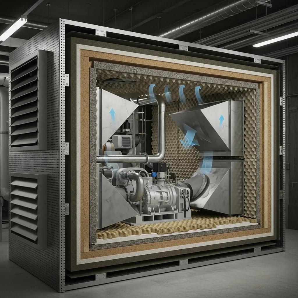
Acoustic enclosures reduce compressor noise by combining barrier transmission loss, absorptive lining to damp internal reflections, and carefully engineered ventilation to control airflow noise; the net effect lowers radiated SPL and can reduce TWA exposure at nearby workstations. Properly designed enclosures attenuate airborne sound through multi-layer shells and internal quilted or fibrous absorbers, while silencers and baffles manage inlet and exhaust flow to prevent aerodynamic noise penalties. Enclosure performance is a trade-off between dBA reduction and cooling/maintenance access; design must maintain continuous-duty cooling for high-pressure compressors while enabling service access and fire-safety considerations. When selected and installed correctly, enclosures can deliver substantial reductions in radiated sound levels, depending on frequency content and ventilation requirements.
Before reviewing material options, consider these enclosure design principles:
- Maintain adequate airflow and thermal management to avoid thermal derating of the compressor.
- Integrate silenced inlet and exhaust pathways to prevent creating new aerodynamic noise sources.
- Provide service access panels and internal mounting features to simplify maintenance without degrading acoustic performance.
This combination of barrier, absorption, and ventilation management defines how an enclosure converts airborne noise sources into attenuated sound levels outside the cabinet.
What Materials and Designs Are Used in Industrial Acoustic Enclosures?
Industrial acoustic enclosures typically combine a rigid outer shell (mild steel or aluminized panels) with internal absorptive layers such as quilted acoustic material, mineral wool, or closed-cell absorbers to attenuate mid to high frequencies. The outer shell provides mass and barrier performance, while inner layers absorb reverberant energy and reduce cavity resonance; multi-layer constructions increase Rw and broadband SPL reduction. Ventilation is managed with lined ducting, silencers, and acoustic louvers to minimize flow noise; designers balance insertion loss versus pressure drop and partition airflow for cooling. Maintenance access is critical: hinged panels and removable sections preserve serviceability while limiting acoustic leakage when sealed.
Acoustic material comparison and design attributes:
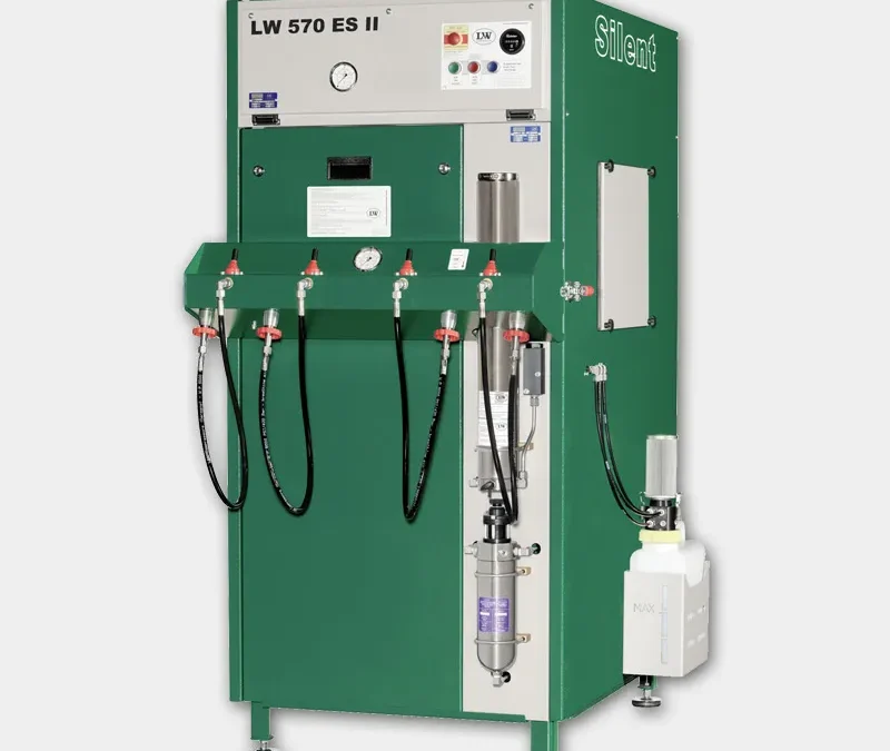
LW Americas emphasizes continuous-duty high-pressure compressor systems with lower RPM and one-piece cast block construction to minimize inherent noise and vibration; these intrinsic design traits pair effectively with custom acoustic enclosures and proper ventilation. LW Americas supports projects with 2D and 3D design drawings and custom project management, enabling site-specific enclosure integration while preserving accessibility and thermal controls.
How Do Acoustic Enclosures Help Achieve OSHA Noise Compliance?
Acoustic enclosures contribute to compliance by reducing the measured SPL at worker locations, thereby lowering time-weighted average (TWA) exposures and potentially moving operations below OSHA action levels and permissible exposure limits. For example, an enclosure *may be capable of achieving* a 20 dBA reduction *under specific conditions*, which *could potentially* change an 88 dBA TWA into a compliant 68 dBA condition for standard exposure calculations, thereby reducing the need for hearing conservation measures. *However, actual performance varies significantly based on factors such as frequency content, installation quality, and the specific environment, making verification through measurement essential.* Measurement involves baseline dosimetry, pre- and post-installation validation using calibrated SPL meters, and documenting time-weighted averages per OSHA 29 CFR 1910.95. Engineering controls like enclosures are preferred on the hierarchy of controls because they reduce exposure at the source without relying on PPE.
Practical steps for validation and documentation include:
- Conduct baseline area and personal dosimetry to identify hotspots and worker TWA.
- Model expected dBA reductions from enclosure specifications and ventilation configurations.
- Perform follow-up dosimetry after installation to verify actual exposure reductions.
These steps ensure that enclosure performance translates into documented compliance and safer work environments.
What Are Effective Vibration Isolation Solutions for Industrial Compressors?
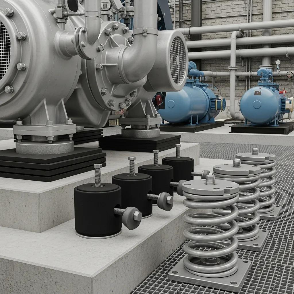
Vibration isolation solutions reduce structure-borne transmission by decoupling the compressor support from the surrounding foundation or piping system, lowering transmitted forces and preventing resonant amplification. Common isolators include anti-vibration pads, neoprene mounts, spring isolators, and inertia bases; selection depends on load, desired natural frequency, and environmental conditions. Proper selection targets a natural frequency significantly lower than the excitation frequencies to ensure adequate attenuation, and installation must consider leveling, anchoring, and flexible piping connections to avoid bypass paths. Good isolation reduces fatigue on connected structures, decreases transmitted tonal components, and complements acoustic treatments to create a quieter facility.
Before comparing products, facilities should apply these selection criteria:
- Calculate static deflection and natural frequency based on load and required attenuation.
- Consider environmental exposure (oil, moisture, temperature) when choosing materials.
- Ensure piping and auxiliary components have flexible connections to avoid reintroducing vibration.
These criteria guide selection from simple pads to engineered spring systems.
How Do Anti-Vibration Pads and Mounts Minimize Facility Vibration?
Anti-vibration pads and mounts reduce transmitted vibration by adding compliant, damping layers between the compressor base and foundation, increasing energy dissipation and shifting the system natural frequency away from excitation bands. Pads made from bonded rubber or neoprene provide simple, cost-effective isolation for small-to-medium loads and also help dampen transient shocks during startup or shutdown. More advanced mounts, such as spring isolators or inertia bases, provide larger static deflections and better low-frequency attenuation for heavy compressors, but require careful leveling and anchoring. Correct installation practices—ensuring full bearing contact, isolator preload as specified, and flexible piping—prevent common performance losses that occur when isolators are incorrectly installed.
Key installation best practices:
- Align and level the machine on the isolators to ensure even load distribution.
- Avoid rigid pipe connections that create bypass vibration paths.
- Verify dynamic performance post-installation with vibration measurements.
Following these steps preserves isolation performance and extends equipment life.
Which Materials Provide Optimal Vibration Dampening for Compressors?
Material selection for vibration dampening balances durability, damping coefficient, load capacity, and environmental resistance; common options include natural rubber, neoprene, polyurethane, and composite elastomers. Natural rubber offers excellent damping and high shear strength but may degrade with oils or ozone; neoprene resists oils and moderate temperatures and is widely used for compressor pads. Polyurethane provides high load-bearing capacity and long-term compression set resistance, making it suitable for heavily loaded isolators and outdoor or oily environments. Composite isolators combine elastomeric layers and metal elements for tailored stiffness and damping across frequency bands.
A comparative view of isolator materials:
- Natural rubber: high damping, limited chemical resistance.
- Neoprene: balanced damping and chemical tolerance.
- Polyurethane: high load capacity, excellent wear resistance.
Selecting the right material based on operating conditions and load expectations ensures sustained isolation performance and lower transmitted vibration.
How Can Facilities Ensure OSHA Compliance for Compressor Noise Exposure?
Facilities ensure OSHA compliance through a structured approach: baseline noise assessment, prioritizing engineering controls (source reduction, enclosures, isolation), implementing administrative controls and PPE when necessary, and documenting monitoring and training.
OSHA sets an action level at 85 dBA TWA (triggering a hearing conservation program) and a permissible exposure limit (PEL) at 90 dBA TWA for an 8-hour shift; NIOSH recommends more conservative limits. Noise mapping, task-based dosimetry, and engineering modeling of enclosure and silencer performance allow facilities to choose controls that lower TWA exposures and reduce reliance on administrative measures. Continuous documentation, periodic re-testing after modifications, and training complete the compliance workflow.
To operationalize compliance, follow these steps:
- Baseline measurement and identification of exposures above 85 dBA.
- Apply engineering controls to reduce exposures at the source.
- Implement hearing conservation program elements where exposures remain above action thresholds.
What Are OSHA Noise Limits and Hearing Conservation Requirements?
OSHA defines the action level at 85 dBA TWA, which obligates employers to implement a hearing conservation program that includes monitoring, audiometric testing, training, and recordkeeping; the PEL is 90 dBA TWA over an eight-hour period. Employers must measure employee exposures using calibrated dosimeters and assess tasks with high SPL to determine the need for engineering controls. When engineering controls are infeasible or during their implementation, administrative controls and properly fitted hearing protection reduce individual exposures. Documentation of monitoring results, medical surveillance where required, and periodic program evaluation complete the employer’s obligations under current rules.
A practical mapping of exposure to action:
- 85 dBA TWA — Hearing conservation program required; engineering controls recommended.
- 90 dBA TWA — PEL threshold; prompt engineering intervention required to reduce exposure.
- >100 dBA — Short allowable exposure; immediate mitigation and PPE mandatory.
Compliance Mapping Table
This table links common exposure levels to allowable exposure times and practical mitigation examples.
How Does LW Americas Support Regulatory Compliance Through Custom Solutions?
LW Americas supports compliance by delivering custom high-pressure compressor systems designed to minimize inherent noise and vibration—features that reduce the engineering burden of downstream controls. The company’s continuous-duty compressors with one-piece cast block construction and lower RPM operation reduce internal excitation and structure-borne energy at the source, while responsive North American support and project management help integrate acoustic enclosures and isolation into facility layouts. LW Americas provides 2D and 3D design drawings that enable clash detection, thermal and acoustic modeling, and installation planning, which accelerates validation and documentation required for compliance. Facilities seeking compliance assessments or engineered solutions can request tailored design and project-management support to validate that implemented controls achieve measured dBA reductions consistent with OSHA requirements.
What Custom Noise Abatement Engineering Solutions Does LW Americas Offer?
LW Americas offers custom engineering services focused on integrated noise and vibration abatement for high-pressure compressor systems, including assessment, CAD deliverables, fabrication coordination, and project management to ensure solutions meet operational and regulatory needs. The workflow typically begins with a site assessment and baseline acoustic/vibration measurement, followed by conceptual design that may combine lower-RPM compressor options, acoustic enclosures, inlet/exhaust silencers, and vibration isolation. LW Americas produces 2D and 3D design drawings that facilitate installation planning, mechanical integration, and verification testing. Project management and North American support ensure on-time delivery and coordination with facility teams for commissioning and post-installation validation.
Service workflow and deliverables include:
- Site assessment and acoustic/vibration baseline.
- Concept and detailed design with 2D/3D CAD packages.
- Fabrication oversight, installation coordination, and post-installation testing.
How Are 2D and 3D Designs Used for Tailored Noise and Vibration Control?
2D and 3D CAD deliverables translate acoustic and vibration design intent into installable layouts, allowing engineers to visualize enclosure clearances, intake/exhaust routing, and isolator placement before fabrication. Three-dimensional models enable clash detection with building structures, piping, and HVAC, and they support computational modeling for airflow and acoustic performance prediction. Deliverables often include enclosure cross-sections, mounting details, and isolation pad locations to guide field installation and testing. These models shorten project timelines, reduce site rework, and provide the documentation needed for regulatory validation and commissioning.
What Industry-Specific Noise Management Solutions Are Available?
Noise management solutions vary by industry priority: diving and medical systems prioritize breathing-air purity and compact enclosures, maritime and firefighting applications emphasize corrosion-resistant materials and seaworthy mounting, and motorsports require compact, high-performance systems with transportable acoustic housings. Each sector imposes constraints—such as portability, environmental exposure, or clean-air compliance—that influence enclosure materials, ventilation strategies, and isolation choices. LW Americas serves these sectors with tailored configurations that reflect operating priorities while preserving continuous-duty performance and serviceability.
How Does Regular Compressor Maintenance Contribute to Noise and Vibration Reduction?
Regular maintenance reduces noise and vibration by preventing the mechanical degradation that creates imbalances, bearing noise, and leaking seals; well-executed maintenance preserves tolerances and prolongs compressor life. Routine inspections catch loose fasteners, worn belts, and air-intake restrictions that elevate SPL and vibration. Lubrication schedules, filter replacement, and valve servicing reduce friction and impact events that manifest as tonal noise. Documenting maintenance actions and trending vibration and acoustic data creates a feedback loop that identifies developing faults before they produce excessive noise or equipment failure.
What Maintenance Practices Help Minimize Compressor Noise and Wear?
A practical maintenance checklist prevents many noise and vibration issues and includes intake filter checks, lubrication, belt tensioning, fastener torque verification, and valve clearance adjustments on scheduled intervals. Inspecting intake and exhaust paths for obstructions or loose ducting prevents aerodynamic noise spikes, while monitoring bearing temperatures and oil condition flags progressive wear. Quick fixes such as tightening mounts or replacing worn dampers often yield immediate noise reductions. Escalation to engineering support is warranted when vibration spectra show bearing frequencies or rotor imbalance patterns beyond routine corrective scope.
Maintenance checklist (task and frequency):
- Inspect and replace intake filters monthly for dusty environments.
- Verify belt tension and alignment quarterly to prevent slipping and squeal.
- Check mounting fasteners and isolation elements monthly for integrity.
These tasks stabilize operational vibration levels and reduce unplanned repairs.
How Is Vibration Analysis Used as a Predictive Maintenance Tool?
Vibration analysis employs sensors and spectral analysis to identify signatures of imbalance, misalignment, bearing defects, and looseness before catastrophic failure occurs; trending amplitude and frequency content over time enables condition-based maintenance. Typical practice uses accelerometers mounted at bearing housings and structural locations, with data logged and trended to detect deviations from baseline. Spectral peaks at bearing defect frequencies or increasing broadband energy indicate specific faults that can be scheduled for repair during planned downtime. Integrating vibration data into maintenance planning reduces emergency repairs, lowers total cost of ownership, and complements acoustic monitoring for a full predictive maintenance program.
Facilities can pair vibration analysis with targeted engineering interventions—such as isolation upgrades or balancing—to address root causes revealed by trend data.