
By Robert Carmichael, LW Americas
Compressed Natural Gas (CNG) fueling compressors are pivotal in modern energy distribution, particularly for industrial and fleet applications. These sophisticated systems not only compress gas for storage but also ensure its safe and efficient delivery. Throughout this article, readers will uncover the intricate engineering principles that underlie CNG compressor design, operational functionalities, and safety features. Understanding the complexities in these systems is essential for optimizing performance and adhering to safety standards. We will explore design features, operational efficiencies, safety considerations, and maintenance protocols that are crucial for effective CNG utilization.
LW Americas is the exclusive North and South American distributor of L&W high-pressure compressors and gas management systems, providing equipment selection, system design, supply, commissioning, and ongoing support for industrial gas and CNG fueling applications. Drawing on that experience, the discussion that follows reflects the technical standards and engineering considerations applied to real-world industrial compressor projects across fleet, public fueling, and process gas environments.
Design Features:
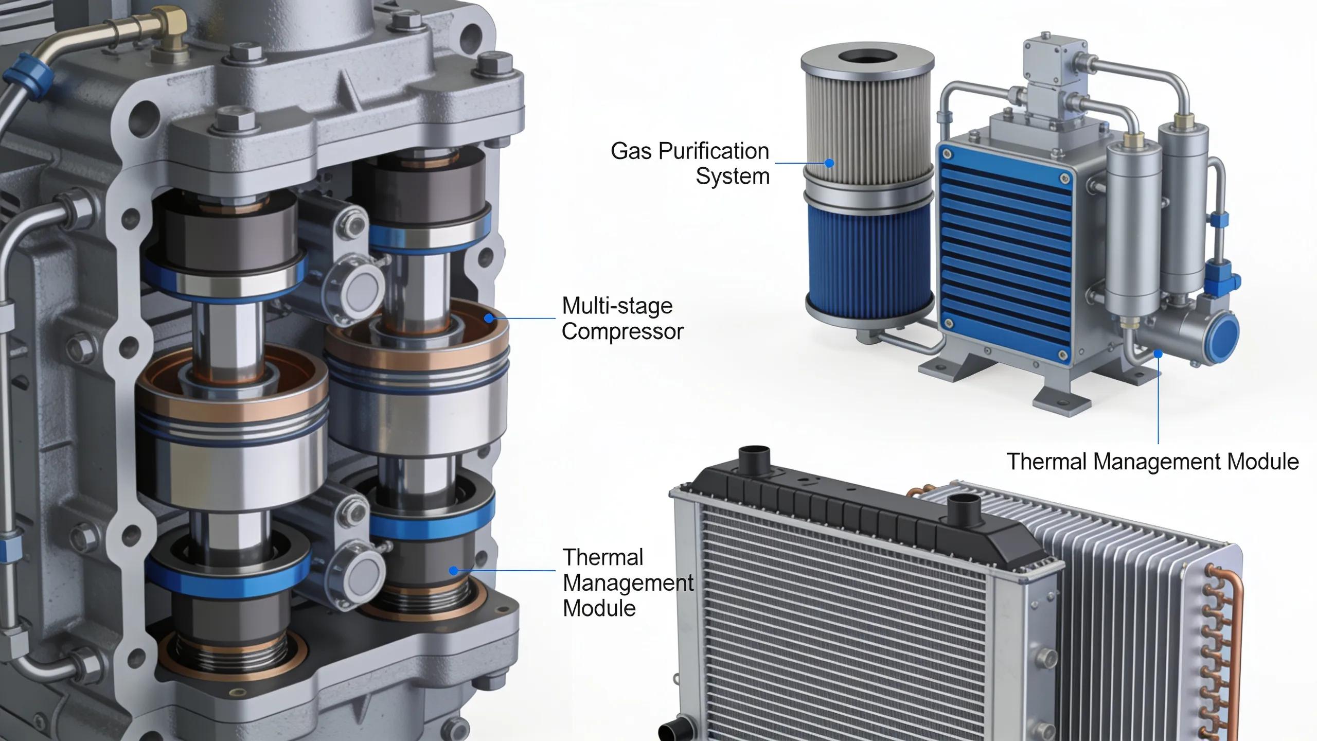
CNG fueling compressors are engineered with specific features that enhance reliability and efficiency. Understanding these design features is vital to optimizing their performance across various applications, from industrial operations to fleet fueling solutions.
Multi-Stage Compression:
Multi-stage compression is foundational to the engineering of high-pressure CNG compressors. Rather than compressing natural gas to storage pressures in a single pass, multi-stage designs incrementally increase gas pressure across successive compression stages, typically achieving final discharge pressures of 3,600 psi (248 bar) or higher. Between each stage, intercoolers remove the heat of compression before the gas enters the next stage. This intercooling is critical: it reduces the specific work required for subsequent compression, protects downstream components from excessive thermal stress, and improves volumetric efficiency throughout the machine. Following the final compression stage, an aftercooler brings the discharge gas down to a temperature suitable for storage and dispensing, and a final moisture separator removes condensed water before the gas enters the high-pressure storage cascade. Pressure management across stages is carefully engineered through interstage pressure ratios, safety relief valves at each stage outlet, and pressure instrumentation to ensure balanced loading and protection against over-compression. This layered approach reduces mechanical strain on individual components, extends compressor service life, and delivers a more consistent, reliable output across the full operating range.
Gas Purification:
Gas purification within a CNG fueling system is a shared responsibility across the overall installation rather than a function attributed solely to the compressor package. In many installations, primary gas conditioning — including bulk moisture removal, odor management, and pressure regulation — is performed upstream of the compressor by the utility or pipeline infrastructure. The compressor package itself may incorporate coalescing filters, inlet moisture separators, and interstage separators to address residual water, lubricating oil carryover, and particulates introduced during the compression process. The extent of filtration integrated into a given compressor package depends on the inlet gas quality, the compressor technology, and the requirements of the end application. Regardless of where purification duties are allocated within the system, maintaining clean, dry gas throughout the compression train is essential: water and oil contamination can degrade valve performance, damage seals, accelerate wear on cylinder components, and reduce the efficiency of downstream storage and dispensing equipment. System designers must account for the full gas-conditioning requirement at the project level rather than relying on any single component to address all purification functions.
Material Compatibility:
Material selection in CNG compressors is governed by the demands of high-pressure natural gas service rather than by natural gas itself being inherently corrosive. Dry, pipeline-quality natural gas is relatively benign to most metals; however, trace contaminants — including hydrogen sulfide, carbon dioxide, water, and compressor lubricants — can affect certain materials over time and must be accounted for during design. Pressure-containing components such as cylinders, heads, and manifolds are typically fabricated from carbon steel or alloy steel, specified in accordance with applicable pressure vessel codes including ASME Section VIII and relevant national or regional equivalents. Seals and elastomers require particular attention: piston rings, rod packing, O-rings, and valve seat materials must be selected for compatibility with natural gas, lubricating oil, and the temperature ranges encountered across each compression stage. Improper elastomer selection can result in swelling, hardening, or extrusion failures, leading to gas leakage and premature component replacement. Valve components, check valves, and fittings used in high-pressure piping and instrumentation must similarly be rated and tested for the service pressure and gas composition in question. A rigorous material review conducted during the design phase — addressing mechanical strength, pressure rating, gas compatibility, and seal performance — is essential to ensuring long-term reliability in CNG compressor packages.
Thermal Management:
Effective thermal management is integral to the design of high-pressure CNG compressor packages, encompassing intercoolers, aftercoolers, and cooling system infrastructure that operate together across every stage of the compression train.
Intercoolers are positioned between successive compression stages to remove the heat of compression before gas enters the next stage. By reducing gas temperature at each interstage point, intercoolers decrease the specific volume of the gas, reducing the work required for subsequent compression and protecting downstream components from thermal overload. In reciprocating compressor packages, intercoolers are typically shell-and-tube or fin-and-tube heat exchangers sized to bring interstage gas temperatures within acceptable limits for the following stage’s valves, piston rings, and cylinder components.
Following the final compression stage, an aftercooler reduces discharge gas temperature to a level suitable for high-pressure storage and dispensing. The aftercooler also promotes condensation of residual moisture, which is subsequently removed by a final moisture separator before gas enters the storage cascade. Discharge temperature leaving the aftercooler is a critical operating parameter: elevated temperatures accelerate elastomer degradation in downstream components and can affect the accuracy of custody transfer measurement.
Cooling medium selection — whether air cooling, facility cooling water, or a dedicated closed-loop cooling circuit — depends on site infrastructure, ambient conditions, and the thermal load of the specific compressor package. Air-cooled packages are common in outdoor installations where facility cooling water is unavailable, while water-cooled configurations offer more consistent thermal performance in high-ambient-temperature environments or where space constraints limit air-cooled heat exchanger sizing.
Temperature monitoring throughout the compression train is a standard feature of the compressor control system. Discharge temperature sensors at each stage outlet, cooling medium outlet temperature instrumentation, and aftercooler discharge temperature monitoring provide continuous data to the control system. High-temperature shutdown setpoints are configured at each stage to initiate a controlled compressor shutdown in the event of cooling system failure, inadequate cooling medium flow, or process upset conditions that would otherwise drive discharge temperatures beyond safe operating limits. Integrating thermal monitoring with the compressor’s safety shutdown logic ensures that thermal events are detected and mitigated before they result in equipment damage or loss of containment.
Operational Efficiency:
Operational efficiency in CNG fueling compressors is influenced by various design and operational strategies. Enhancements in this area not only contribute to improved performance but also result in economic benefits for users.
Continuous-Duty Design:
Continuous-duty capability in a CNG compressor package is the result of deliberate engineering decisions made across the compressor’s design, cooling system, component sizing, and operational envelope — not an inherent consequence of simply operating the machine continuously. A compressor rated for continuous duty has been designed and tested to sustain full-load operation over extended periods without exceeding the thermal, mechanical, or fatigue limits of its components.
Key contributors to continuous-duty capability include adequate cooling capacity at the intercoolers and aftercooler to maintain acceptable discharge temperatures under sustained load; component sizing — including cylinder bore, rod diameter, bearing surfaces, and crosshead design — sufficient to handle the cumulative mechanical stresses of uninterrupted operation; lubrication system design that maintains adequate oil film thickness and cleanliness at all operating temperatures; and valve construction and seating materials selected for the cyclic stress of high-cycle continuous service.
Operating within the equipment’s rated design envelope is equally important. Running a compressor at or near its maximum rated pressure and flow continuously, without adequate cooling or lubricant condition monitoring, will compromise component life regardless of the machine’s nominal continuous-duty rating. For high-demand applications such as fleet fueling depots or industrial process gas supply, continuous-duty compressor packages are selected precisely because their design margins, cooling systems, and component specifications have been validated for the intended operating regime — but sustained performance depends on adherence to the manufacturer’s operating limits and maintenance requirements throughout the service life of the installation.
Storage Sizing:
Proper storage sizing is vital to accommodate the demands placed on CNG fueling systems. Balancing storage tanks appropriately between intermittent and continuous fueling needs helps optimize system performance. From large industrial sites to fleet applications, appropriate storage sizing minimizes disruptions caused by fluctuations in demand, leading to smoother operation and increased efficiency.
Heat Recovery:
Implementing heat recovery systems within CNG fueling stations offers significant efficiency gains. By capturing waste heat generated during the compression process, facilities can repurpose this energy for other operational needs, such as preheating incoming gas or other heating applications. This not only improves overall efficiency but also enhances sustainability practices in CNG operations.
Safety Considerations:
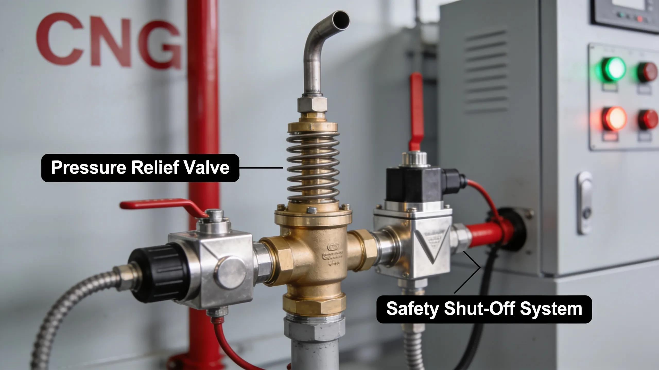
Safety in CNG fueling installations is governed by a layered framework that combines engineered protective systems, hazardous area design, operational procedures, and compliance with applicable codes and standards. Each layer addresses a distinct failure mode, and no single measure is considered sufficient in isolation.
Over-Pressure Protection:
CNG compressors operate at high discharge pressures, typically up to 3,600 psi (248 bar) or higher, and over-pressure protection is a fundamental design requirement at every stage of the compression train. Pressure relief valves (PRVs) are installed at each interstage outlet and at the final discharge to provide automatic pressure relief in the event of a process upset, blocked outlet, or control system failure. High-pressure shutdown switches provide an independent layer of protection, initiating a controlled compressor shutdown before pressures reach the relief valve set points. Pressure instrumentation is continuously monitored by the compressor control system, and operating pressure limits are enforced through both software logic and hardwired safety circuits.
Emergency Shutdown Systems:
Emergency shutdown (ESD) systems are integral to CNG compressor packages and station designs. An ESD system is capable of initiating a rapid, controlled shutdown of all compression and gas-handling equipment in response to detected hazardous conditions, including gas detection alarms, fire signals, operator activation, or loss of critical utilities. ESD logic is typically implemented in a dedicated safety relay system or safety-rated programmable logic controller (PLC) that operates independently of the main process control system. ESD activation sequences include closing of automated block valves, de-energizing the compressor drive, and isolating the station from the gas supply. ESD systems are designed, tested, and documented in accordance with functional safety principles, and periodic proof testing is required to verify that safety functions perform as intended.
Gas Detection:
Continuous gas detection is a standard requirement in enclosed or semi-enclosed CNG fueling facilities. Fixed catalytic bead or infrared gas detectors are positioned at low points, within compressor enclosures, and near potential leak sources such as valve manifolds, high-pressure fittings, and dispenser connections. Detection of combustible gas concentrations at or above defined alarm thresholds — typically expressed as a percentage of the Lower Explosive Limit (LEL) — triggers a graduated response: a first-stage alarm may activate ventilation and issue an operator alert, while a second-stage alarm initiates ESD and facility lockout. Gas detection systems are integrated with the ESD logic and are regularly tested and calibrated in accordance with the detector manufacturer’s requirements and applicable standards.
Hazardous Area Classification:
Areas within and surrounding a CNG fueling station are classified as hazardous locations in accordance with applicable electrical area classification standards. In North American installations, classification is typically performed in accordance with the National Electrical Code (NEC), NFPA 30A, and NFPA 52, designating zones where flammable gas-air mixtures may be present. All electrical equipment installed within classified areas — including motors, lighting, instrumentation, and control panels — must be rated and certified for the applicable hazardous location classification. In international installations, IEC 60079 series standards define equivalent zone classifications and equipment requirements. Proper area classification documentation and equipment selection are prerequisites for facility commissioning and regulatory approval.
Applicable Codes and Standards:
CNG fueling installations are subject to a defined body of codes and standards that govern system design, equipment selection, installation, and operation. Key references applicable to North American installations include NFPA 52 (Vehicular Natural Gas Fuel Systems Code), which covers the design and installation of CNG fueling facilities; ASME B31.3 (Process Piping) and ASME B31.8 (Gas Transmission and Distribution Piping Systems) for high-pressure piping design; ASME Section VIII for pressure vessel fabrication; and CSA B108 (Natural Gas Fuelling Stations Installation Code) for Canadian installations. Equipment manufacturers typically certify compressor packages to applicable standards such as those published by the American Petroleum Institute (API) or relevant national bodies. Compliance with these standards is a legal obligation in most jurisdictions and provides the baseline assurance necessary for insurance, permitting, and safe facility operation.
Specialized Components and Safety Features:
Beyond system-level protections, individual compressor components contribute to the overall safety architecture. Automatic block valves isolate the compressor from the gas supply upon shutdown. Pressure-rated check valves prevent backflow of high-pressure gas into the compression stages or inlet piping. Rupture discs may be incorporated as secondary over-pressure devices in certain high-pressure applications. Continuous monitoring of parameters including discharge temperature, interstage pressures, lube oil pressure, and vibration allows the control system to detect developing faults and initiate protective shutdowns before failures propagate. The integration of these component-level protections with the station-wide ESD and gas detection systems constitutes the complete safety layer for a CNG fueling installation.
Training and Procedures:
Engineered safety systems must be supported by structured operational and maintenance procedures and by trained personnel who understand the hazards associated with high-pressure natural gas. Operators should be familiar with ESD activation and reset procedures, gas detection response protocols, emergency isolation procedures, and the requirements for safe entry into classified areas. Maintenance personnel performing work on pressure-containing components must follow documented procedures for depressurization, purging, and isolation. Regular training, competency assessment, and procedure review form the human element of the safety framework and are essential to maintaining operational integrity over the life of the installation.
Core Engineering Principles
Fundamental engineering principles guide the design and functionality of CNG fueling compressors. These principles ensure that compressors not only meet performance standards but also operate safely and efficiently.
The core principles involve balancing high-pressure requirements with stringent safety measures. Ensuring that engineering practices prioritize both efficiency and safety enables the development of robust CNG fueling solutions that can withstand demanding operational environments.
LW Americas applies these engineering principles across its work in specifying, supplying, and commissioning high-pressure compressor packages — selecting and integrating equipment that incorporates multi-stage compression, thermal management, materials engineering, and safety system architecture into complete, code-compliant installations for fleet fueling, public CNG infrastructure, and industrial process gas applications. Each project is configured to the specific inlet conditions, discharge pressures, flow requirements, and site constraints of the application — reflecting the recognition that rigorous equipment selection and system integration at the project development stage is the most reliable foundation for long-term system performance.
Fleet vs. Industrial Applications
CNG compressors serve materially different operational requirements depending on the application, and system design — including compressor sizing, storage configuration, redundancy philosophy, and duty cycle — must reflect those differences. Four principal application categories merit distinct consideration.
Fleet Fueling at Private Depots:
Private fleet fueling depots serve a defined number of vehicles — buses, refuse trucks, delivery vehicles, or utility fleets — that return to a central facility on a predictable schedule, typically overnight or at shift changes. Compressor sizing for a private depot is driven by the fleet’s total daily gas consumption, the available fueling window, and whether the operation employs time-fill (slow-fill overnight) or fast-fill (dispensing at full flow rate). Time-fill systems can utilize smaller, continuously running compressors that charge vehicles slowly over several hours, whereas fast-fill depots require larger compressors and high-pressure storage cascades capable of sustaining multiple simultaneous dispenses. Redundancy requirements at private depots vary: some operators accept a single compressor with a scheduled maintenance plan, while critical fleets — particularly transit agencies or emergency services — specify parallel compressor trains to ensure continuous availability. Duty cycles at these sites tend to be consistent and predictable, simplifying compressor selection and sizing calculations.
Public CNG Fueling Stations:
Public fueling stations serve a variable and less predictable mix of light-duty, medium-duty, and heavy-duty vehicles, including long-haul trucking where dispensing speed is critical to driver productivity. These stations require fast-fill capability across multiple dispensers simultaneously, necessitating larger compressor capacities, high-pressure cascade storage with priority fill control, and robust dispenser infrastructure. Compressor redundancy is a stronger commercial and operational imperative at public stations, where downtime directly impacts revenue and customer retention. Control systems at public stations must manage cascade bank sequencing, dispenser communication, and payment systems, adding integration complexity relative to private depot applications. Design standards and codes applicable to public CNG stations, particularly NFPA 52 in North America, impose specific requirements around dispenser setbacks, ventilation, emergency shutdown access, and signage.
Industrial Process Gas Applications:
Industrial applications of natural gas compression extend beyond vehicle fueling to include gas injection, pipeline booster service, gas gathering, and process gas supply for manufacturing or power generation facilities. In these contexts, compressors are selected and configured to different specifications than fueling applications: flow rates may be expressed in standard cubic feet per minute (SCFM) or million standard cubic feet per day (MMSCFD), inlet pressures may vary significantly from the relatively stable utility supply pressure seen in fueling stations, and outlet pressure requirements depend on the receiving process or pipeline. Duty cycles in industrial process applications are often continuous, with high availability and low mean time to repair (MTTR) as primary design drivers. Compressor selection in these applications is governed primarily by project-specific requirements and applicable process industry codes, including ASME B31.3 for piping design and, where relevant, API standards for packaged reciprocating or screw compressors. It should be noted that API 11P — which covers packaged reciprocating compressors for oil and gas production service — may be referenced in certain industrial gas compression projects, but many CNG fueling and process gas installations are specified principally to NFPA, ASME, CSA, and project-specific requirements rather than API standards, and the applicable reference documents should be confirmed for each project. Redundancy, remote monitoring, and integration with distributed control systems (DCS) or SCADA platforms are common requirements.
Implications for Compressor Selection:
The distinctions between these application categories underscore that there is no universal CNG compressor specification. Sizing a compressor package requires a thorough analysis of daily gas demand, peak flow rate, inlet gas conditions, available fueling window, storage volume, target dispense pressure, redundancy philosophy, and applicable codes. Engaging qualified engineering resources early in the project development process — before equipment is specified or purchased — is essential to ensuring that the selected system will meet operational requirements reliably and safely throughout its service life.
LW Americas supports clients through this process, providing application analysis, equipment selection, system design, and commissioning services for CNG fueling and industrial gas compression projects. As the exclusive distributor of L&W high-pressure compressor systems in the Americas, LW Americas brings direct access to a proven equipment platform alongside the project engineering and integration capabilities needed to configure complete, site-specific installations. Early engagement with LW Americas enables project developers to define the correct compressor capacity, storage configuration, and redundancy strategy before procurement — avoiding the costly redesign and schedule impacts that result from equipment selections made without a complete site and application assessment.
Safety and Compliance Standards
Compliance with safety standards is not only a legal requirement but also essential for ensuring safe operations in CNG facilities. Familiarity with relevant regulations empowers operators to achieve optimal safety and operational performance.
Adhering to safety and compliance standards minimizes risks associated with CNG operations, protecting personnel and equipment. Awareness of these standards is critical for maintaining operational integrity and achieving industry best practices.
Maintenance Protocols for Long-Term Efficiency
Sustaining the reliability and efficiency of industrial CNG compressor packages over their service life requires a structured maintenance program that extends well beyond routine visual inspections. Best-practice maintenance programs for high-pressure compressors combine scheduled preventive maintenance with ongoing condition monitoring and, where appropriate, predictive maintenance technologies.
Scheduled Preventive Maintenance:
Preventive maintenance tasks are performed at manufacturer-specified intervals and include valve inspection and replacement, piston ring and rod packing assessment, filter element replacement, lubricant and coolant service, belt or coupling inspection, and torque verification of pressure-containing fasteners. Valve condition is among the most maintenance-sensitive aspects of reciprocating CNG compressors: worn or damaged valves reduce volumetric efficiency, increase discharge temperatures, and — if not addressed — can result in valve failure and unplanned shutdown. Maintenance intervals should be derived from the manufacturer’s documentation and adjusted based on observed component condition and operating history rather than applied generically.
Condition Monitoring:
Continuous and periodic condition monitoring provides the data necessary to detect developing faults before they result in equipment damage or unplanned downtime. Standard condition monitoring practices for industrial CNG compressor packages include:
-
Vibration analysis: Accelerometers mounted on compressor frames, bearing housings, and piping monitor vibration signatures across the operating frequency range. Deviations from established baseline vibration profiles can indicate bearing wear, imbalance, looseness, or developing valve issues, often well in advance of a detectable performance change.
-
Oil analysis: Periodic laboratory analysis of compressor lubricating oil — including viscosity measurement, particle count, elemental analysis for wear metals, and oxidation assessment — provides an indirect view of internal component condition. Elevated iron, copper, or aluminum concentrations in an oil sample can signal early bearing, cylinder, or crosshead wear.
-
Temperature trending: Continuous logging of discharge temperatures at each stage outlet, interstage temperatures, and cooling medium temperatures establishes a baseline from which deviations can be identified. A gradual rise in stage discharge temperature under constant load conditions may indicate valve inefficiency, reduced cooling performance, or changes in inlet gas composition.
-
Filter differential pressure monitoring: Monitoring the pressure drop across inlet filters, coalescing filters, and interstage separators provides a direct indication of filter loading. Rising differential pressure signals that a filter element is approaching its service limit; operating beyond this point reduces flow, increases compressor work, and risks upstream contamination from element bypass.
-
Valve inspection and performance assessment: In reciprocating compressors, individual valve performance can be evaluated through cylinder pressure-volume (P-V) analysis, where available, or through comparative monitoring of interstage pressures and temperatures. Anomalies in interstage conditions relative to expected thermodynamic performance are often the earliest indicator of valve inefficiency.
Predictive Maintenance Technologies:
Industrial CNG compressor installations increasingly incorporate predictive maintenance platforms that aggregate condition monitoring data — vibration, temperature, oil analysis results, and operational parameters — into a continuous equipment health picture. Remote monitoring systems transmit real-time compressor data to centralized platforms where trend analysis, anomaly detection algorithms, and maintenance scheduling tools assist operations and reliability teams in optimizing maintenance timing and avoiding both premature component replacement and unplanned failures. Integration of compressor control system data with a plant SCADA or distributed control system (DCS) allows maintenance events to be correlated with process conditions, improving the diagnostic value of the collected data.
A well-structured maintenance program — combining manufacturer-specified preventive tasks with systematic condition monitoring and predictive tools — is the most reliable means of sustaining compressor availability, protecting capital equipment investment, and ensuring that CNG fueling or process gas supply capacity remains continuously available to the operations it supports.
Key Design and Application Considerations by CNG System Type
Industrial CNG compressors are not meaningfully compared by simple labels such as “multi-stage” or “single-stage,” as virtually all high-pressure CNG compressors employ multiple compression stages. Rather, engineers and procurement teams evaluate compressor packages against the specific parameters of the application. The table below identifies the principal design and application factors that govern compressor selection across the primary CNG use cases:
|
Consideration |
Fleet Fueling (Time-Fill) |
Fleet Fueling (Fast-Fill) |
Public Fueling Station |
Industrial / Process Gas |
|---|---|---|---|---|
|
Typical discharge pressure |
Up to 3,600 psi (248 bar) |
Up to 3,600 psi (248 bar) |
Up to 3,600 psi (248 bar) |
Application-specific |
|
Compressor sizing basis |
Daily fleet demand over fill window |
Peak simultaneous dispense rate |
Peak multi-dispenser demand |
Required flow rate (SCFM / MMSCFD) |
|
Storage requirement |
Moderate; buffer for overnight fill |
High; cascade storage for fast fill |
High; cascade with priority control |
Application-specific |
|
Duty cycle |
Continuous or scheduled |
Demand-driven with peak periods |
Demand-driven; high peak variability |
Typically continuous |
|
Redundancy philosophy |
Single train often acceptable |
Parallel trains common for critical fleets |
Parallel trains typical |
High availability; low MTTR required |
|
Key applicable standards |
NFPA 52, ASME B31.3, ASME VIII |
NFPA 52, ASME B31.3, ASME VIII |
NFPA 52, ASME B31.3, ASME VIII |
ASME B31.3, project-specific (API standards where applicable) |
Maintenance intervals and efficiency ratings for CNG compressor packages are established by the equipment manufacturer based on actual operating conditions, compressor type (reciprocating designs predominate in high-pressure CNG fueling applications, with rotary screw configurations used in certain lower-pressure or high-flow applications), lubrication system, gas quality, and duty cycle — and should be obtained from the manufacturer’s documentation and verified through operational experience rather than assigned generically by application category.